Brake mechanism of fishing line wheel

A brake mechanism and fishing reel technology, applied in fishing reels, fishing, applications, etc., can solve the problems of not being able to meet its requirements, limited space, etc., and achieve the effect of large braking force

Active Publication Date: 2013-05-08
NINGBO HAIBO GRP CO LTD
View PDF1 Cites 3 Cited by
  • Summary
  • Abstract
  • Description
  • Claims
  • Application Information

AI Technical Summary

Problems solved by technology

However, due to the limited space between the main shaft and the reel, it is impossible to increase the brake pads infinitely to increase the braking force during actual assembly. Therefore, for fishing lines with increasing strength (such as fishing lines with strong braided lines), The braking force provided by the current brake pad group has been far from meeting its requirements, so the braking mechanism of the existing fishing reel needs to be further improved

Method used


Image

  • Brake mechanism of fishing line wheel
  • Brake mechanism of fishing line wheel
  • Brake mechanism of fishing line wheel

Examples


Embodiment Construction

[0020] The present invention will be further described in detail below in conjunction with the accompanying drawings and embodiments.

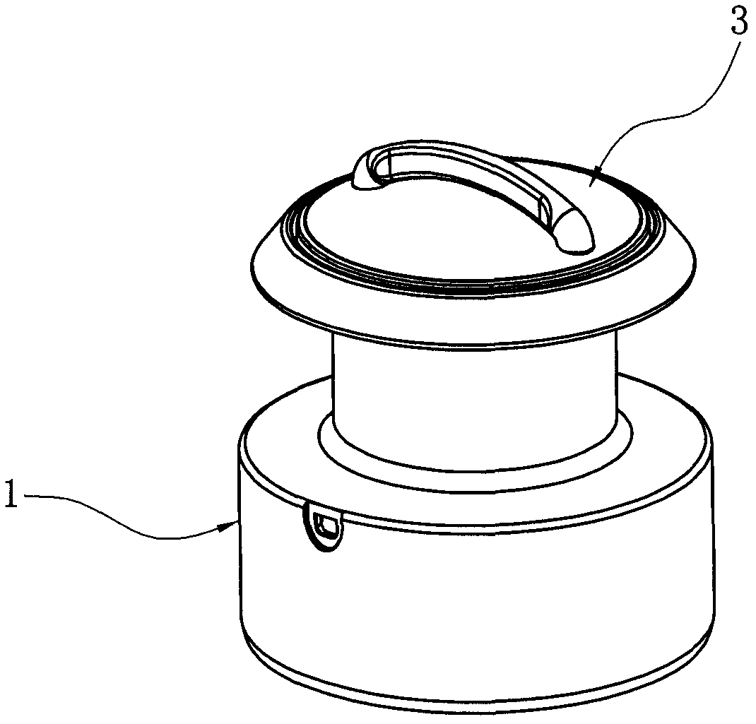
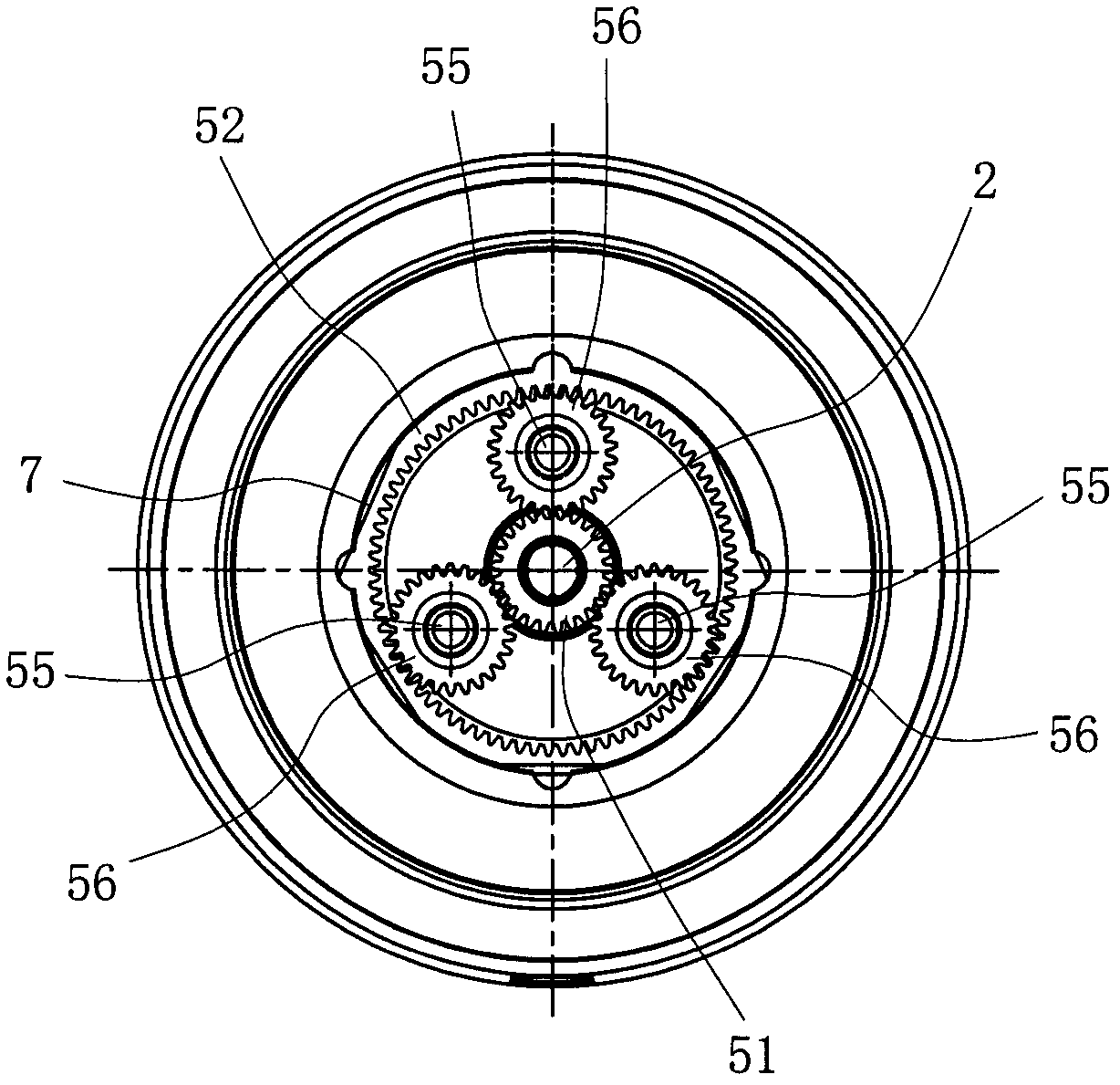
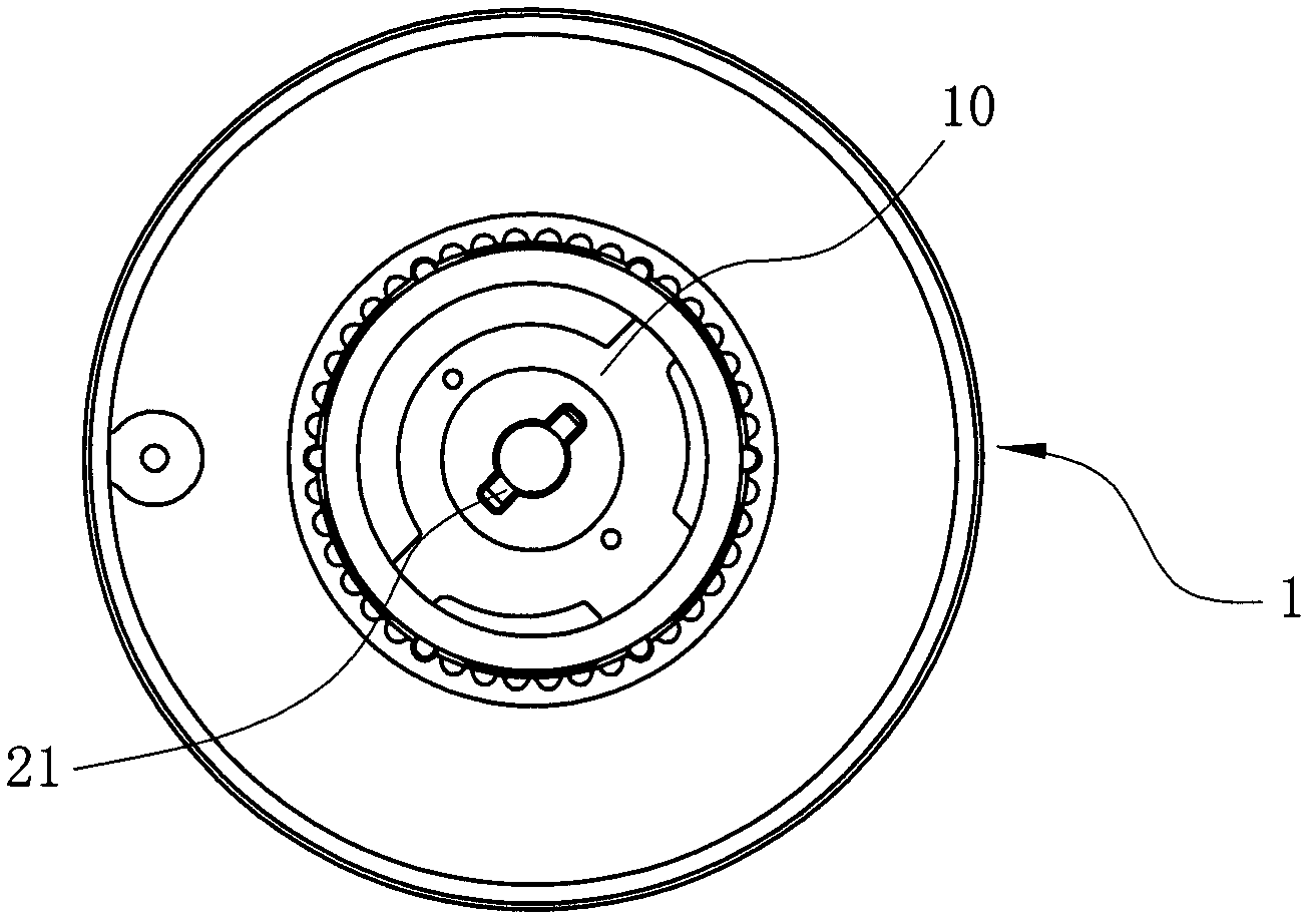
[0021] like Figure 1 to Figure 6 As shown, the braking mechanism of the fishing reel is located on the reel 1, which includes the main shaft 2 of the fishing reel, the adjustment knob assembly 3 connected to the top of the main shaft and the brake pad group 4 set on the main shaft, wherein the adjustment knob assembly 3 is The conventional assembly includes an adjustment knob 31 for controlling the braking force, a nut 32 threaded on the top of the main shaft, a spring 33 and a button seat 34 which are located under the nut and sleeved on the main shaft in turn. The above-mentioned wire wheel 1 has a wall 11 through which the main shaft passes, and the wall separates the inner cavity of the wire wheel into an upper cavity 12 adjacent to the adjustment knob assembly 3 and a lower cavity 13 below the wall 11 . The above-mentioned brake pad set...


PUM


Abstract

The invention relates to a brake mechanism of a fishing line wheel. The brake mechanism is improved on the basis of a conventional adjusting button assembly and a brake pad set positioned in the upper cavity of the line wheel, namely a planet gear mechanism positioned between the adjusting button assembly and the brake pad set is also arranged in the upper cavity; the planet gear mechanism comprises a sun gear, an inner gear, a planet gear and upper and lower cover plates; the inner gear is axially limited on the inner wall of the upper cavity and linked with the line wheel; the sun gear is sleeved on a main shaft in a loose manner, and a sun gear seat is fixed on the sun gear; one of the upper and lower cover plates is linked with the main shaft, and the other cover plate is opposite to the sun gear seat; and meanwhile, the main shaft above the sun gear seat and the main shaft below the sun gear seat are respectively sleeved with a first brake washer in a loose manner. By means of the planet gear mechanism, the friction force which acts on the line wheel is amplified exponentially, so in a limited space, a high braking force can be obtained without excessive increase in the brakepad set, and a big brake of the fishing line wheel is obtained.

Description

technical field [0001] The invention relates to a fishing reel, in particular to a brake mechanism in the fishing reel. Background technique [0002] Most of the existing fishing reel braking mechanisms adopt a combined structure of brake pads, especially more common on spinning-type fishing reels. Such as the Chinese Patent Authorization Announcement No. CN201528603U "Front Adjusting Device for Fishing Reel" discloses such a brake mechanism. There are springs, button seats, brake pads, sleeves and wire wheels that are successively set on the main shaft. The adjustment knob for controlling the brake pads is located on the top. When in use, the nut is driven to rotate by rotating the adjustment knob, and the nut rotates downward Movement, compressing the spring, the spring is pressed to generate elastic force and transmitted to the brake pad through the button seat, after the brake pad is pressed, the friction force of the reel rotating around the main shaft increases, and t...

Claims


Application Information

Patent Timeline
Patent Type & Authority Patents(China)
IPC IPC(8): A01K89/02
Inventor 徐伟俊李晓道贺定芳
Owner NINGBO HAIBO GRP CO LTD
Why Eureka
Try Eureka