Steel bar clamping mechanism on steel bar truss forming machine

A steel truss and clamping mechanism technology, applied in the direction of clamping, metal processing machinery parts, support, etc., can solve the problems of high manufacturing cost, large installation space, sparse connection, etc., and achieve low production cost, compact structure, and easy adjustment Effect

Active Publication Date: 2012-04-18
浙江亿洲机械科技有限公司
View PDF6 Cites 2 Cited by
  • Summary
  • Abstract
  • Description
  • Claims
  • Application Information

AI Technical Summary

Problems solved by technology

[0003] There are four steel bar clamping mechanisms on the existing truss forming machine. The clamping mechanism is composed of a clamping part with a jaw and an oil cylinder that controls the opening and closing of the jaw. One clamping mechanism can only clamp one steel bar at a time. , so the steel bar clamping mechanism used on the existing truss forming machine has defects such as large total installation space, high manufacturing cost, and sparse connection between each other.

Method used


Image

  • Steel bar clamping mechanism on steel bar truss forming machine
  • Steel bar clamping mechanism on steel bar truss forming machine
  • Steel bar clamping mechanism on steel bar truss forming machine

Examples


Embodiment Construction

[0019] The present invention will be further described below in conjunction with the accompanying drawings.

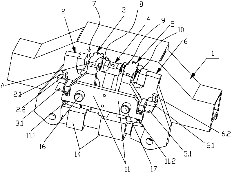
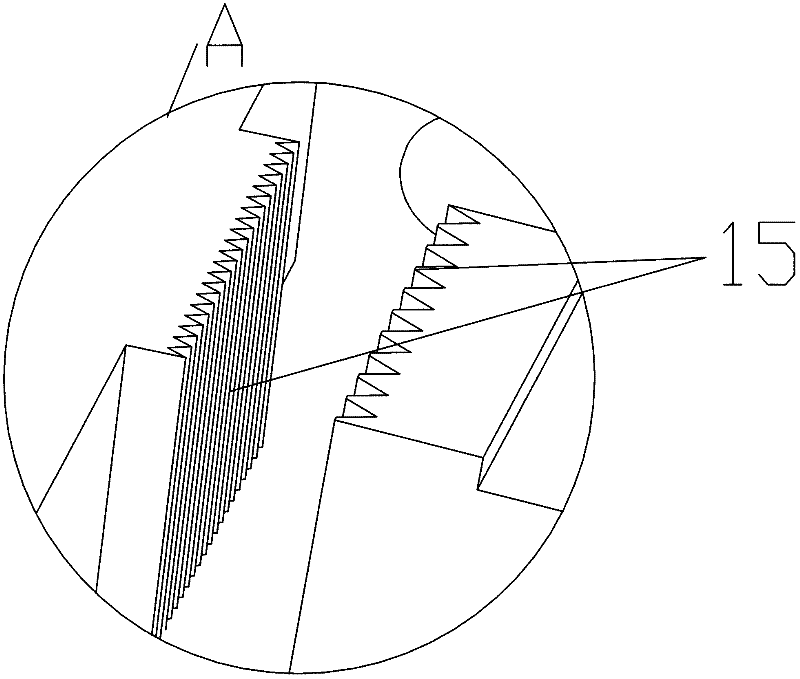
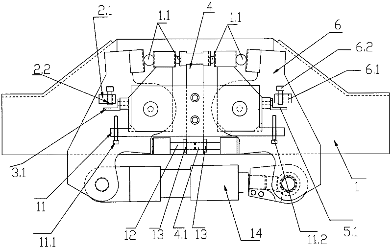
[0020] to combine figure 1 , figure 2 , image 3 As shown, a steel bar clamping mechanism on a steel bar truss forming machine, which includes a mounting seat 1 slidingly fitted on the truss support, a guide rail is provided on the frame of the truss forming machine, and the mounting seat 1 is slidable on the guide rail; the mounting seat 1 One side is provided with the first active arm 2, the first passive arm 3, the clamp holder 4, the second passive arm 5 and the second active arm 6 in order from left to right. figure 1 and image 3 , the left and right sides mentioned here are image 3 shown left and right.

[0021] The first active arm 2, the first passive arm 3, the second passive arm 5 and the second active arm 6 are all hinged with the mounting base 1, and the chuck holder 4 is fixedly connected with the mounting base 1; the upper end of the first active ...


PUM


Abstract

The invention discloses a steel bar clamping mechanism on a steel bar truss forming machine. The steel bar clamping mechanism comprises a mounting base (1), wherein one lateral surface of the mounting base (1) is provided with a first driving arm (2), a first driven arm (3), a chuck fixed base (4), a second driven arm (5) and a second driving arm (6) sequentially from left to right; a first chuck(7) is formed between the upper end of the first driving arm (2) and the upper end of the first driven arm (3); a second chuck (8) is formed between the upper end of the first driven arm (3) and the upper end of the chuck fixed base (4); a third chuck (9) is formed between the upper end of the chuck fixed base (4) and the upper end of the second driven arm (5); a fourth chuck (10) is formed between the upper end of the second driven arm (5) and the upper end of the second driving arm (6); and the four chucks can clamp steel bars simultaneously under the driving of a driving device, namely the steel bar clamping mechanism can clamp the four steel bars simultaneously. The steel bar clamping mechanism belongs to the technical field of clamping mechanisms.

Description

technical field [0001] The invention relates to a clamping mechanism, in particular to a steel bar clamping mechanism on a steel bar truss forming machine. Background technique [0002] At present, in the construction of buildings, railways, bridges and other industries, in order to improve the bonding strength of concrete, steel bars are usually welded into steel bar trusses of different cross-sectional shapes and embedded in concrete. The section of the steel truss is generally triangular. The triangular truss includes an upper hanging bar and two lower hanging bars. The upper hanging bar and the two lower hanging bars are welded together by a corrugated steel bar bent into a wave shape. The upper hanging bar and the two corrugated bars The three wave crests are welded together, and the two sides of the middle waist of the two waves are welded together with the two lower string bars respectively. During product forming, the two hanging bars and the two steel bars to be b...

Claims


Application Information

Patent Timeline
Patent Type & Authority Applications(China)
IPC IPC(8): B23Q3/00
Inventor 陈增光
Owner 浙江亿洲机械科技有限公司
Why Eureka
Try Eureka