Method and structure for installing electricity generator on unmanned plane

A technology of generators and drones, which is applied to aircraft parts, transportation and packaging, etc., to achieve stable operation, improve work efficiency, and improve flight safety.

Inactive Publication Date: 2012-04-18
贵州贵航无人机有限责任公司
5 Cites 4 Cited by

AI-Extracted Technical Summary

Problems solved by technology

However, the current technology for installing gene...

Method used

Embodiment. Generator of the present invention is installed horizontally as shown in Fig. 1, and the arrow among Fig. 1 represents the flight direction of aircraft. The method of installing the generator on the UAV, the generator is a JF3.5kW/28V DC generator, the input shaft of the generator is a spline shaft, and the radial runout of the spline shaft is not more than 0.2mm; the input shaft of the generator is The coupling is directly and rigidly connected with the flywheel disc at the output end of the engine to ensure rapid and accurate transmission of the engine output torque and minimize power loss during transmission. The coupling is provided with a spline hole connected with the generator and several connection holes connected with the flywheel disc at the output end of the engine; the axis of the spline hole and several connection holes should be aligned with the center The hole and the connection hole are coaxial. To ensure the concentricity requirements of the generator and the engine. The frame of the drone is provided with a mounting bracket, an adapter plate is installed on the mounting bracket, a fixed bracket is provided behind the adapter plate, the adapter plate is sandwiched by the fixed bracket and the mounting bracket, and the generator is suspended by bolts Installed behind the adapter plate. The adapter plate is made of a high-strength aluminum alloy cold-rolled plate with a concave structure to ensure the rigidity of the adapter plate and alleviate the impact of the high-speed engine on the generator to carry a large dynamic load and improve the reliability of the product. sex.
The present invention is in order to be able to use JF3.5kW/28V dc generator on the unmanned plane of power with piston engine, installation design technical scheme of the present invention is to set about research and design parts from following four aspects, guarantee 3.5kW/ Special requirements for 28V DC generator installations. 1. Improve transmission efficiency. Only by adopting a rigid coupling between the flywheel disc at the output end of the engine crankshaft and the input end of the 3.5kW/28V DC generator, can the power loss be minimized during the transmission process. Since the maximum speed of the engine is 5800rpm, and the normal operating speed must be above 4000rpm, the ordinary elastic coupling can no longer meet the requirements. In addition, due to the structural limitations of the aircraft, it is impossible to design an e...

Abstract

The invention discloses a method and a structure for installing an electricity generator on an unmanned plane. The electricity generator is a JF 3.5kw/28V direct-current electricity generator, wherein the input shaft of the electricity generator is a spline shaft; the radial runout of the spline shaft is not more than 0.2mm; and the input shaft of the electricity generator is rigidly connected with a flying wheel plate of an output shaft of an engine directly through a coupler, so that the output torque of the engine is ensured to be quickly and accurately transmitted and the power loss is minimal in a transmission process. By the method and the structure, the installation is reliable, the running is stable, overmuch engine output power is not used, the power demand of pickaback and task equipment of the unmanned plane can be ensured when the unmanned plane flies, the engine output power consumed by the electricity generator is ensured to be minimal when power equipment normally runs, and the working efficiency of the 3.5kw/28V direct-current electricity generator is improved.

Application Domain

Technology Topic

Image

  • Method and structure for installing electricity generator on unmanned plane
  • Method and structure for installing electricity generator on unmanned plane

Examples

  • Experimental program(1)

Example Embodiment

[0014] The following describes the present invention in further detail with reference to the accompanying drawings and embodiments, but it does not serve as a basis for any limitation of the present invention.
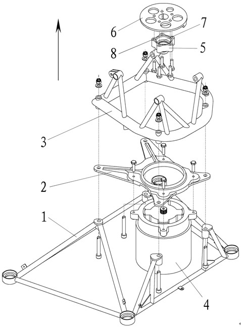
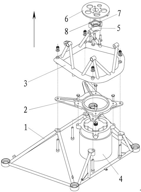
[0015] Examples. Such as figure 1 The generator of the present invention shown is installed horizontally, figure 1 The arrow in indicates the flight direction of the aircraft. The method of installing a generator on the UAV, the generator is a JF3.5kW/28V DC generator, the input shaft of the generator is a spline shaft, and the radial runout of the spline shaft is not more than 0.2mm; the input shaft of the generator is The coupling is directly rigidly connected with the flywheel at the output end of the engine to ensure rapid and accurate transmission of engine output torque and minimize power loss during transmission. The coupling is provided with a spline hole connected with the generator and several connecting holes connected with the flywheel disc at the engine output end; the axis of the spline hole and the several connecting holes should be aligned with the center of the flywheel disc at the engine output end The hole and the connecting hole are coaxial. To ensure the concentricity requirements of the generator and engine. The frame of the drone is provided with a mounting bracket, an adapter plate is installed on the mounting bracket, a fixing bracket is arranged behind the adapter plate, the adapter plate is clamped back and forth between the fixing bracket and the mounting bracket, and the generator is suspended by bolts Installed behind the adapter plate. The adapter plate is made of a high-strength aluminum alloy cold-rolled plate to make a concave structure to ensure the rigidity requirements of the adapter plate and relieve the impact of the high-speed engine on the generator, so as to carry a large dynamic load and improve the reliability of the product Sex.
[0016] The structure formed according to the aforementioned method of installing a generator on a drone includes a mounting bracket 1 mounted on the drone frame, the mounting bracket 1 is provided with an adapter plate 2, and the adapter plate 2 is provided with a fixing bracket 3 , The mounting bracket 1, the adapter plate 2 and the fixing bracket 3 are connected by bolts; the rear side of the adapter plate 2 is connected with the generator 4, and the generator 4 is connected with the flywheel 6 at the output end of the engine through the coupling 5. The coupling 5 is provided with a central hole 7 and a plurality of connecting holes 8, and the axis of the central hole 7 is coaxial with the uniform center of the plurality of connecting holes 8. The fixed bracket 3 and the mounting bracket 1 are triangular truss structures.
[0017] In order to be able to use the JF3.5kW/28V DC generator on the unmanned aerial vehicle powered by the piston engine, the installation design technical scheme of the present invention is to study and design parts from the following four aspects to ensure 3.5kW/28V DC power generation Special requirements for machine installation. 1. Improve transmission efficiency. Only by adopting a rigid coupling between the flywheel at the output end of the engine crankshaft and the input end of the 3.5kW/28V DC generator can the power loss be minimized during transmission. Since the maximum engine speed is 5800rpm and the normal working speed must be above 4000rpm, ordinary elastic couplings can no longer meet the requirements. In addition, due to the limitation of the aircraft structure, it has been impossible to design an elastic coupling that meets the requirements, so rigid couplings The device is the most suitable connection method. At the same time, the fatigue strength of rigid couplings of the same magnitude is much higher than that of elastic couplings. The only disadvantage of rigid couplings is that they must ensure high-precision concentricity installation requirements. 2. Transmit engine output torque quickly and accurately. Since the 3.5kW/28V DC generator requires the minimum excitation speed to be greater than 3000rpm, the commonly used belt drive can no longer meet the requirements. At the same time, the weather resistance and reliability of the V-belt are not high, which brings safety hazards to high-altitude flight. In order to ensure the rapid and accurate transmission of the engine output torque, the invention adopts a direct connection mode. 3. Ensure high concentricity installation requirements. The three important parts to ensure the concentricity requirements are the coupling, the adapter plate and the fixing bracket. The concentricity of the axis of the spline hole on the coupling, the axis of the hole and the axis of the hole on the circle is required to ensure that the hole on the adapter plate and the JF3.5kW/28V DC generator top stop circle are positioned to ensure that the generator input end and the engine The concentricity of the crankshaft must be below 0.05mm, which is the key technology of this design. In the specific process implementation process, special fixtures are used to ensure that the overall assembly error is less than 0.12mm. The design of JF3.5kW/28V DC generator proposes that the radial runout of the spline shaft is below 0.2mm, which can ensure its basic requirements for stable operation and meet the overall technical status. 4. Ensure the rigidity requirements of the overall structure. The 3.5kW/28V DC generator has a dead weight of 15kg. In order to effectively alleviate the impact of the high-speed engine on the engine, the adapter plate adopts high-strength aluminum alloy cold-rolled plate, and the structure adopts a recessed design, which can carry a larger load. Dynamic load. In order to ensure the overall rigidity requirements of the power plant installation, a triangular truss structure is adopted on the fixed support and the installation support to ensure the impact resistance of the support.

PUM

no PUM

Description & Claims & Application Information

We can also present the details of the Description, Claims and Application information to help users get a comprehensive understanding of the technical details of the patent, such as background art, summary of invention, brief description of drawings, description of embodiments, and other original content. On the other hand, users can also determine the specific scope of protection of the technology through the list of claims; as well as understand the changes in the life cycle of the technology with the presentation of the patent timeline. Login to view more.

Similar technology patents

Gauge leveling device

Owner:廖丹霞

Anti-deformation wall switch

PendingCN113345748AAvoid deformation transferReliable installationTumbler/rocker switch detailsStructural engineeringMechanical engineering
Owner:浙江格兰电气有限公司

Classification and recommendation of technical efficacy words

  • Smooth running
  • Reliable installation

Two-stage friction type dual-mass flywheel

InactiveCN101446328ASmooth runningStart softVibration suppression adjustmentsClutchFriction effect
Owner:CHONGQING GUANGDA IND +1

Insertion strip for cars and mounting structure thereof

InactiveCN101314346AReliable installationSimplify manufacturing stepsVehicle componentsEngineeringHelix
Owner:KATAYAMA KOGYO CO LTD
Why Eureka
Try Eureka