Water flow accelerating pipe

A technology for accelerating pipes and water flow, which is applied in the main water supply pipeline, sewage pipeline system, water supply pipeline system, etc., and can solve the problems of increased consumption of water pumps, increased energy consumption, and increased electricity bills

Inactive Publication Date: 2012-04-18
SHANGHAI PANDA MACHINEGRP CO LTD
View PDF4 Cites 3 Cited by
  • Summary
  • Abstract
  • Description
  • Claims
  • Application Information

AI Technical Summary

Problems solved by technology

The outlet pipe of the water pump and the main water supply pipe are connected at 90 degrees, so that when several pumps run at the same time, the water flows into some T-shaped intersections A, and when the water flows through the T-shaped intersections, the flow velocity of the water is seriously hindered and the pressure loss is very large (see figure 1 ), so that the useless work consumed by the water pump will increase, resulting in an increase in energy consumption when the user uses it (mainly an increase in electricity bills)

Method used


Image

  • Water flow accelerating pipe
  • Water flow accelerating pipe
  • Water flow accelerating pipe

Examples


Embodiment Construction

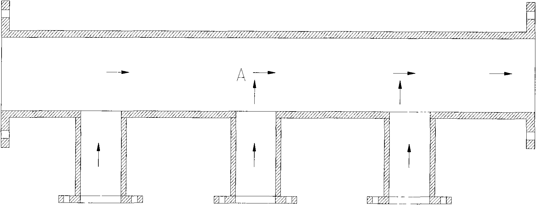
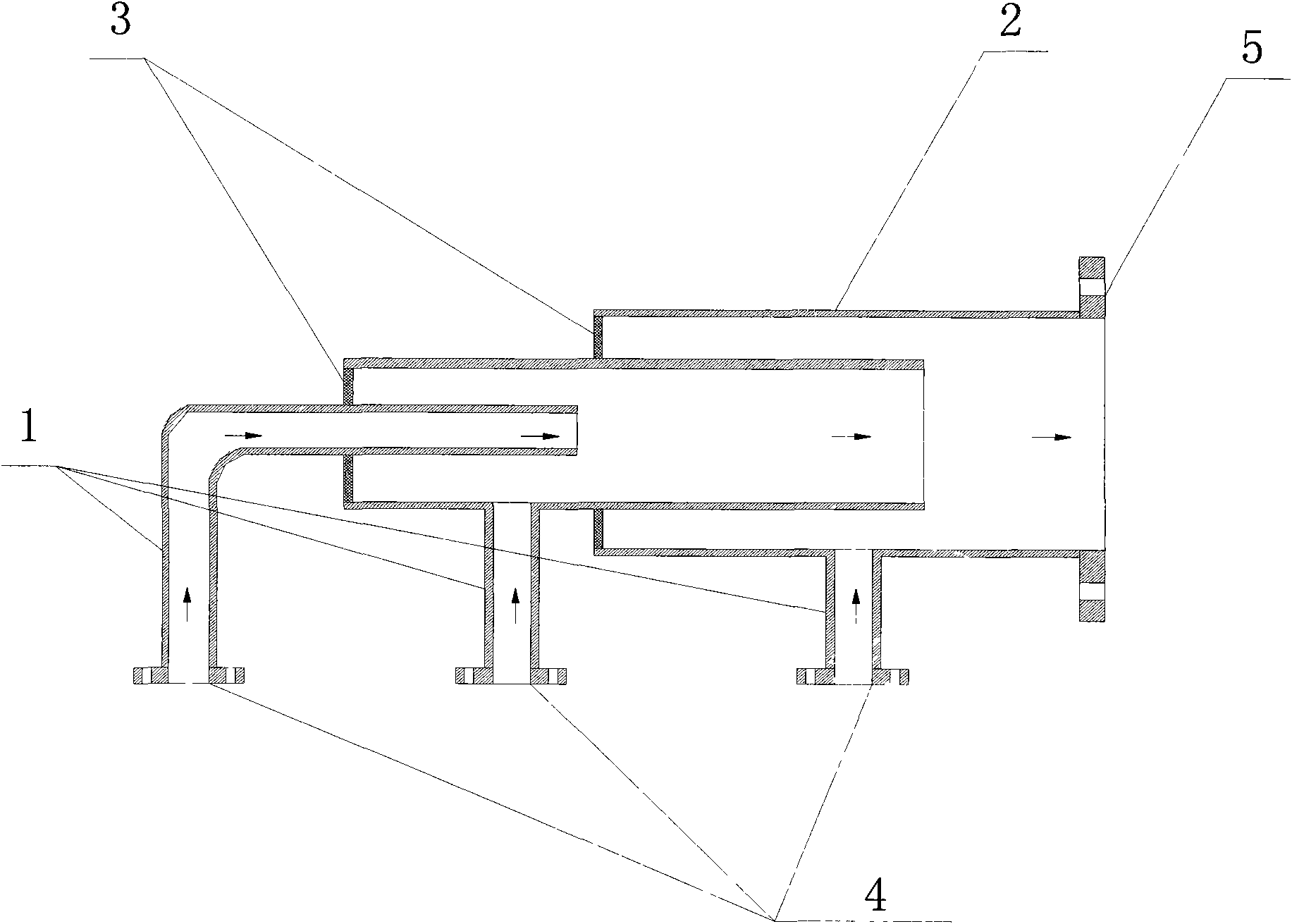
[0008] Such as figure 2 A water flow accelerating tube shown: it is composed of a branch pipe 1, a combination pipe 2, a sealing plate 3, and a flange 4. One end of the branch pipe 1 is welded to the combination pipe 2, and the other end is a water inlet connection port, and the water inlet branch 1 pipe Combination pipe 2 is composed of multiple pipes with different diameters welded by sealing plate 3. The combination pipe 2 is also welded with a flange nozzle 5 connected to the water outlet main pipe. The size of the pipe combination 2 is according to the flow direction (The arrows in the figure indicate the direction of water flow) are arranged from small to large. The small pipes extend into the large pipes and extend to the position of the connecting branch beyond the large pipes. The diameter of the large pipes is enough to satisfy itself and the previous stage. In this way, when the water in the small pipe enters the large pipe, it avoids direct impact on the water inl...


PUM


Abstract

The invention relates to a water flow accelerating pipe, which consists of a plurality of pipes with different diameters in a combining way. The pipes are combined and arranged from small to large in the flow direction of water. Small pipes stretches into large pipes and are connected with the large pipes in a welding way through sealing plates. When water in the small pipes enter the large pipes, the situation that impacts are caused to inlet water of the large pipes is avoided, the high-pressure water in the small pipes provides forward pushing force to accelerate water flow speed, the losses of water pressure in the pipes are reduced and the energy saving goal is achieved.

Description

1: Technical field [0001] The invention relates to a water flow accelerating pipe used in a water supply and drainage system, in particular to a water outlet main pipe of a water supply and drainage equipment. Two: background technology [0002] In the water supply equipment in the prior art, there is generally a water outlet main pipe at the water outlet of the water pump to connect several pumps to form a parallel water supply. The outlet pipe of the water pump and the main water supply pipe are connected at 90 degrees, so that when several pumps run at the same time, the water flows into some T-shaped intersections A, and when the water flows through the T-shaped intersections, the flow velocity of the water is seriously hindered and the pressure loss is very large (see figure 1 ), so that the useless work consumed by the pump will increase, resulting in an increase in energy consumption (mainly an increase in electricity bills) when the user uses it. Three: Invention c...

Claims


Application Information

Patent Timeline
Patent Type & Authority Applications(China)
IPC IPC(8): E03B7/09E03F3/04
Inventor 池学聪谭红全
Owner SHANGHAI PANDA MACHINEGRP CO LTD
Why Eureka
Try Eureka