Irradiation device

A light irradiation device and light source technology, which is applied to lighting devices, components of lighting devices, optics, etc., can solve the problems of excimer lamp shaking, lamp damage, and damage to the uniformity of illumination of the light irradiation surface, and achieve in-plane uniformity High, the effect of avoiding damage

Inactive Publication Date: 2012-04-18
USHIO DENKI KK
View PDF4 Cites 0 Cited by
  • Summary
  • Abstract
  • Description
  • Claims
  • Application Information

AI Technical Summary

Problems solved by technology

[0013] However, in this cooling method, the excimer lamp shakes due to the turbulence generated inside the outer tube, and there is a problem that the lamp is broken due to the vibration.
[0014] Furthermore, due to the shaking of the excimer lamp, the size and position of the region irradiated with light from the excimer lamp change, which impairs the uniformity of illuminance on the light irradiation surface of the object to be processed.

Method used


Image

  • Irradiation device
  • Irradiation device
  • Irradiation device

Examples


Embodiment Construction

[0106] Hereinafter, embodiments of the present invention will be described in detail.

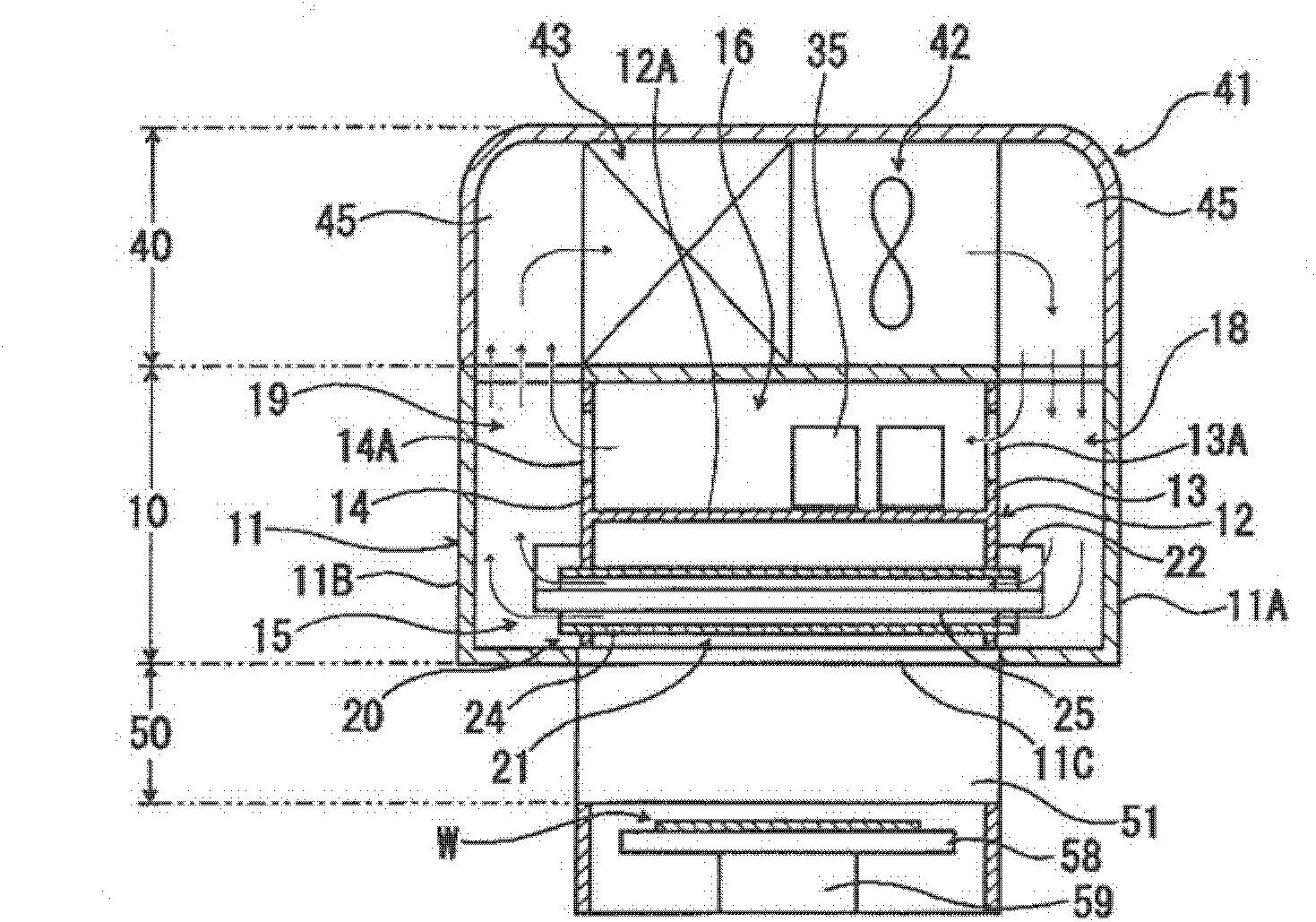
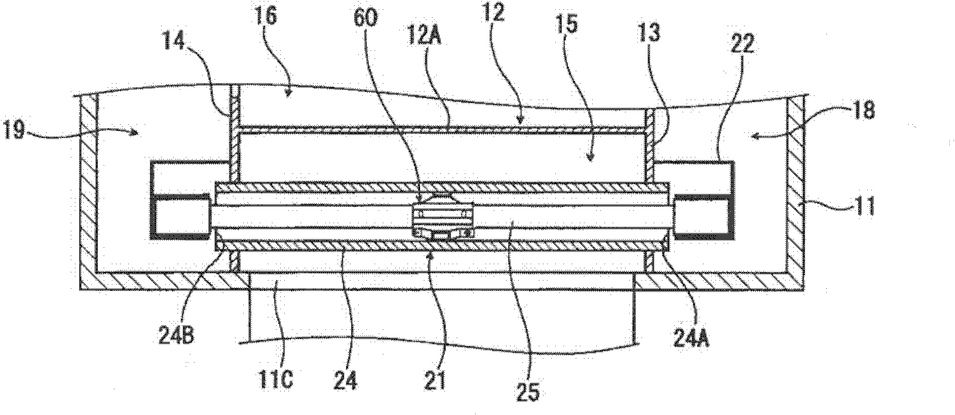
[0107] figure 1 It is an explanatory diagram showing the outline of the internal structure of one configuration example of the ultraviolet irradiation device of the present invention, figure 2 is enlarged figure 1 A cross-sectional view of a part of the UV irradiation device shown.

[0108] This ultraviolet irradiation device is basically constituted by a light source unit 10, a cooling unit 40, a light guide unit 50, and a power supply unit (not shown).

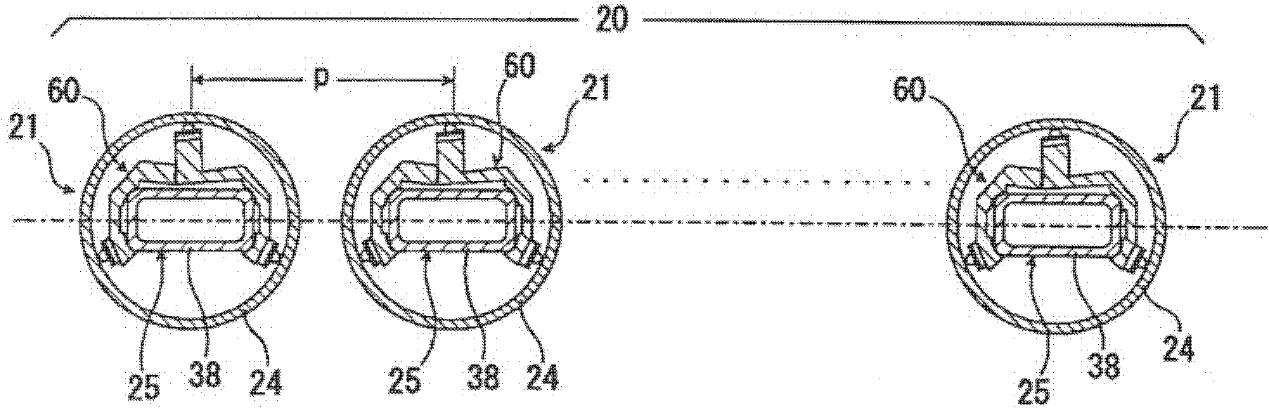
[0109] The light source unit 10 includes a light source unit case member 11 having a light irradiation opening 11C opened downward and having a box-like shape as a whole.

[0110] Inside the light source case member 11, a frame body 12 with a cross-sectional shape of approximately H shape is provided, and the frame body 12 is formed by a planar partition wall 12A extending in the horizontal direction, and the light source part case ...


PUM


Abstract

The invention provides an irradiation device which can provide the illumination intensity of an irradiation face of a processed object and has inner face uniformity in irradiation processing. The irradiation device includes a light source element which is maintained by two lengthwise end parts via a frame body. A rectangular strip lamp is vertically arranged along the lengthwise direction. When the lamp is turned on, the two ends along the lengthwise direction are arranged via the frame body, and the lamp is composed of a cylindrical outer sleeve with the inside forming a cooling wind circulating path. The inside of the outer sleeve is provided with a supporting part which directly supports a local position of the lamp along the lengthwise direction to the outer sleeve. The supporting part is connected with four corners of the lamp, and clamps and maintains the lamp. The supporting part is made of an insulating material. The supporting part is provided with an inner face pressing against the outer sleeve. An outer sleeve pressing part is provided with an elastic member.

Description

technical field [0001] The present invention relates to a light irradiation device. Background technique [0002] LCD panel 70 as Figure 8 As shown, it is a structure in which liquid crystal is sealed between two glass plates. The first glass plate 71 on which the alignment film 74 is formed and the second glass plate 75 on which the color filter 76 , the transparent electrode 77 , and the alignment film 78 are formed face each other on one side through a spacer member 79 . It is disposed and formed by forming a liquid crystal layer 80 between the first glass plate 71 and the second glass plate 75 . [0003] In the manufacturing process of this kind of liquid crystal panel 70, it is known to carry out the reaction treatment of the liquid crystal panel material (pretilt angle finding) processing, PSVA) technology (refer to Patent Document 1). In this technique, by irradiating ultraviolet rays to the liquid crystal panel while applying a voltage, the optically active mater...

Claims


Application Information

Patent Timeline
Patent Type & Authority Applications(China)
IPC IPC(8): G02F1/1337
CPCF21V19/008G02F1/133553G02F1/133788
Inventor 竹添法隆菅敏幸
Owner USHIO DENKI KK
Why Eureka
Try Eureka