Air conditioning device
An air conditioning and control device technology, applied in space heating and ventilation, gas circulation refrigerators, heating methods, etc., can solve the problems of higher blowing temperature, affecting user comfort, lowering blowing temperature, etc. energy effect
- Summary
- Abstract
- Description
- Claims
- Application Information
AI Technical Summary
Problems solved by technology
Method used
Image

Examples
Embodiment approach 1
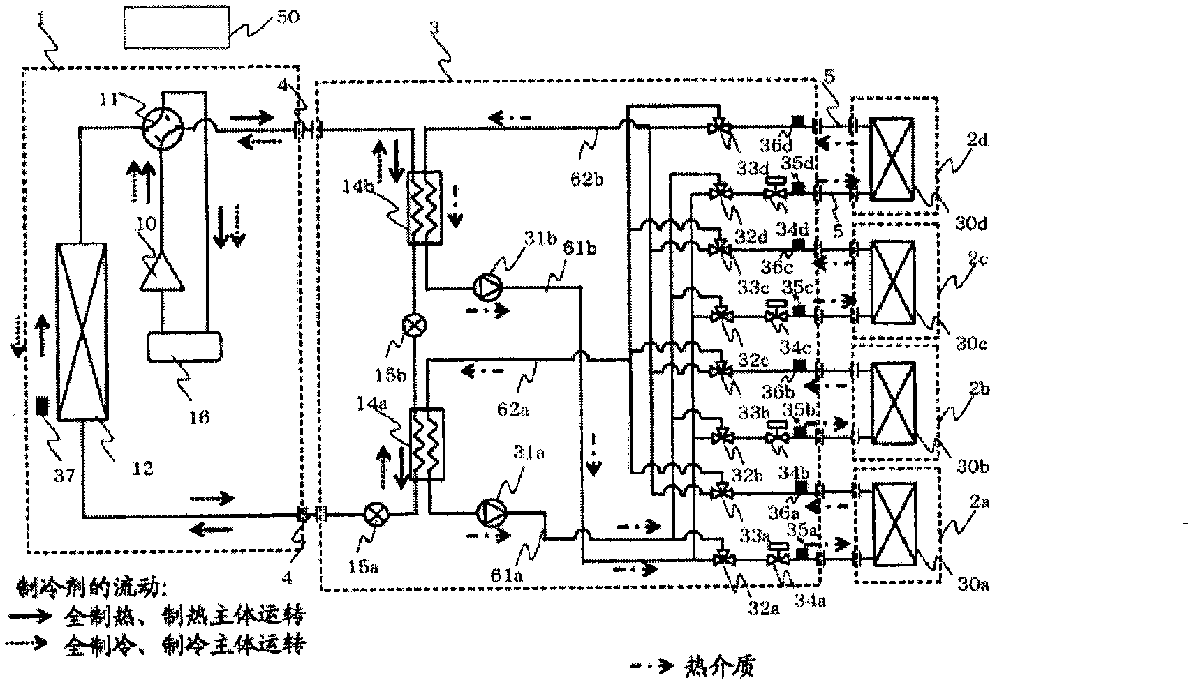
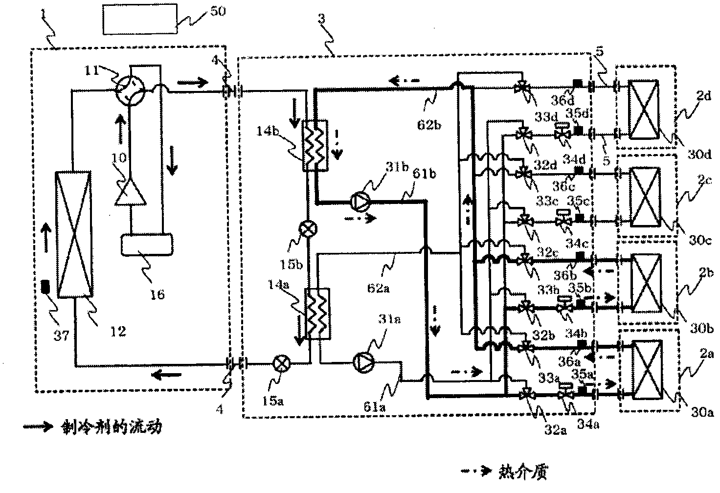
[0018] figure 1 It is a system circuit diagram of the air-conditioning apparatus in Embodiment 1 of this invention. In the air-conditioning apparatus according to Embodiment 1, the compressor 10, the four-way valve 11 as a refrigerant flow switching device, the heat source side heat exchanger 12, the heat exchangers related to heat medium 14a, 14b, the electronic expander Expansion devices 15a, 15b such as valves, and an accumulator 16 constitute a refrigeration cycle. Refrigerant circulates in the refrigeration cycle. Here, the heat exchanger related to heat medium 14a corresponds to the first heat exchanger related to heat medium. The heat exchanger related to heat medium 14b corresponds to the second heat exchanger related to heat medium. Furthermore, the expansion device 15a corresponds to the first expansion device, and the expansion device 15b corresponds to the second expansion device.
[0019] In addition, between the heat medium converter 3 and the use-side heat e...
Embodiment approach 2
[0110] Figure 7 It is a system circuit diagram showing the refrigerant side circuit of the air-conditioning apparatus according to Embodiment 2 of the present invention. In Embodiment 2, check valves 13a, 13b, 13c, and 13d are provided in the heat source machine 1, and other structures are the same as those in Embodiment 1. Hereinafter, the differences between Embodiment 2 and Embodiment 1 will be mainly described.
[0111] During the heating only operation and the heating main operation, the refrigerant passing through the four-way valve 11 flows into the heat medium relay unit 3 through the check valve 13b. In addition, during the cooling only operation and the cooling main operation, the refrigerant flowing out of the heat source side heat exchanger 12 flows into the heat medium relay unit 3 through the check valve 13 a. In addition, the refrigerant flowing out of the heat medium converter 3 and returning to the heat source unit 1 passes through the check valve 13c and f...
Embodiment approach 3
[0115] In the refrigerant side circuits of Embodiments 1 and 2 above, the heat exchangers related to heat medium (14a, 14b) are arranged so that the refrigerant flows in series on the heat source unit 1 side, but in Embodiment 3, in the heating only operation, In the cooling only operation, the refrigerant is arranged so that the two heat exchangers related to heat medium 14a, 14b flow in parallel. In addition, during the heating-main operation and the cooling-main operation, the arrangement is such that part of the refrigerant flowing into the heat medium converter 3 from the heat source unit 1 flows in series in the heat exchangers 14a and 14b related to heat medium, and the rest A part flows through either the heat exchanger related to heat medium 14a or the heat exchanger related to heat medium 14b.
[0116] Figure 8 It is a system circuit diagram showing the refrigerant side circuit of the air-conditioning apparatus according to Embodiment 3 of the present invention. O...
PUM
 Abstract
Description
Claims
Application Information
 - R&D
- Intellectual Property
- Life Sciences
- Materials
- Tech Scout
- Unparalleled Data Quality
- Higher Quality Content
- 60% Fewer Hallucinations
Browse by: Latest US Patents, China's latest patents, Technical Efficacy Thesaurus, Application Domain, Technology Topic, Popular Technical Reports.
© 2025 PatSnap. All rights reserved.Legal|Privacy policy|Modern Slavery Act Transparency Statement|Sitemap|About US| Contact US: help@patsnap.com