Multi-mode multi-band power amplifier module

A technology of power amplifier and power amplification, which is applied in the direction of power amplifier, amplifier, gate control amplifier, etc., and can solve the problems of increasing the size and cost of the transmitter

Active Publication Date: 2012-04-18
QUALCOMM INC
View PDF6 Cites 22 Cited by
  • Summary
  • Abstract
  • Description
  • Claims
  • Application Information

AI Technical Summary

Problems solved by technology

Thus the transmitter may require a relatively large number of power

Method used


Image

  • Multi-mode multi-band power amplifier module
  • Multi-mode multi-band power amplifier module
  • Multi-mode multi-band power amplifier module

Examples


Embodiment Construction

[0014] The word "exemplary" is used herein to mean "serving as an example, instance, or illustration." Any design described herein as "exemplary" should not necessarily be construed as preferred or advantageous over other designs.

[0015] A multi-mode multi-band power amplifier (PA) module capable of supporting multiple modes and multiple frequency bands is described herein. The PA module can be used in various electronic devices such as wireless communication devices, cellular phones, personal digital assistants (PDAs), handheld devices, wireless modems, laptop computers, cordless phones, bluetooth devices, consumer electronic devices, etc. . For clarity, the following describes the use of a PA module in a wireless communication device.

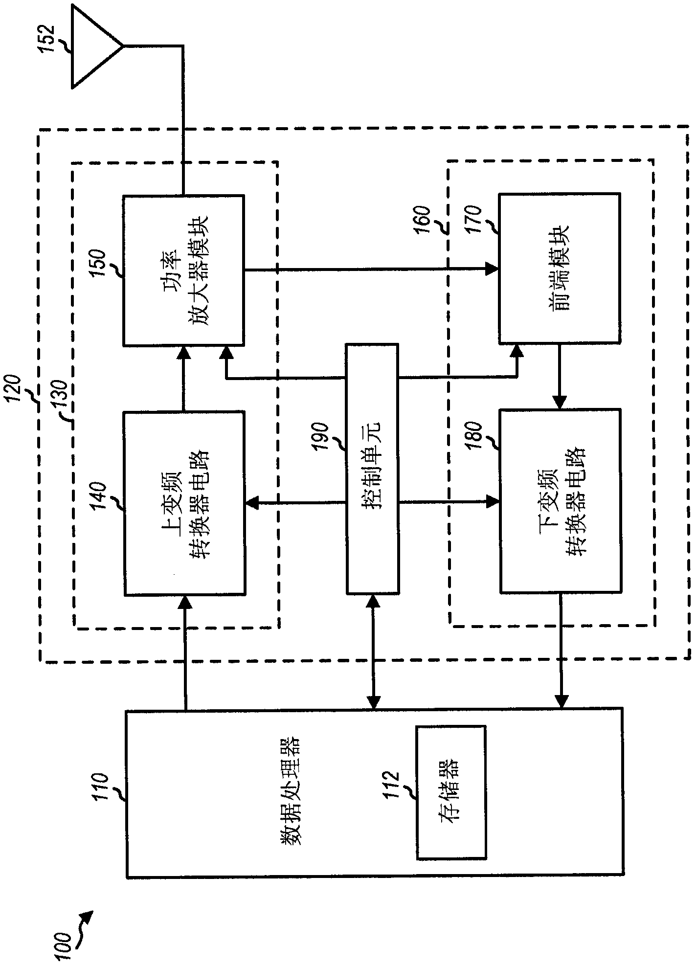
[0016] figure 1 A block diagram of an exemplary design of a wireless communication device 100 is shown. In this exemplary design, wireless device 100 includes data processor 110 and transceiver 120 . The transceiver 120 includes (i) a...


PUM


Abstract

A multi-mode multi-band power amplifier (PA) module is described. In an exemplary design, the PA module includes multiple power amplifiers, multiple matching circuits, and a set of switches. Each power amplifier provides power amplification for its input signal when selected. Each matching circuit provides impedance matching and filtering for its power amplifier and provides a respective output signal. The switches configure the power amplifiers to support multiple modes, with each mode being for a particular radio technology. Each power amplifier supports at least two modes. The PA module may further include a driver amplifier and an additional matching circuit. The driver amplifier amplifies an input signal and provides an amplified signal to the power amplifiers. The additional matching circuit combines the outputs of other matching circuits and provides an output signal with higher output power. The driver amplifier and the power amplifiers can support multiple output power levels.

Description

[0001] Claim of priority under 35 U.S.C. §119 [0002] This patent application asserts U.S. Provisional Serial No. 61 / 177,527, filed May 12, 2009, entitled "MULTI-MODE MULTI-BAND POWER AMPLIFIER AND ANTENNA FRONT END MODULE" Priority to the application, the provisional application assigned to the present assignee, is hereby expressly incorporated herein by reference. technical field [0003] The present invention relates generally to electronic devices, and more particularly to power amplifier (PA) modules for transmitters. Background technique [0004] In a wireless communication system, a transmitter may process (eg, encode and modulate) data to generate output samples. The transmitter may further condition (eg, convert to analog, filter, frequency upconvert, and amplify) the output samples to generate an output radio frequency (RF) signal. The transmitter can then transmit the output RF signal to the receiver via a wireless channel. A receiver may receive the transmit...

Claims


Application Information

Patent Timeline
IPC IPC(8): H04B1/04
CPCH03F1/0277H03F3/72H04B1/0458H04B1/0483H03F2203/7236H03F3/24H04B1/04
Inventor 阿里斯托泰莱·哈奇克里斯托斯培·何·西伊巴巴克·内贾蒂盖伊·克莱门斯诺曼·L·小弗雷德里卡居坎瓦尔·辛格·萨霍塔马尔科·卡西亚内森·M·普莱彻赵瑜托马斯·A·迈尔斯
Owner QUALCOMM INC
Why Eureka
Try Eureka