

Minute pump for clutch
A clutch cylinder and housing technology, applied in clutches, mechanical equipment, etc., can solve the problems of impact, complex structure, affecting the service life of the cylinder
Inactive Publication Date: 2012-04-25
芜湖博格汽车零部件有限公司
View PDF5 Cites 4 Cited by
- Summary
- Abstract
- Description
- Claims
- Application Information
AI Technical Summary
Problems solved by technology
[0002] The clutches in the current automobile operating mechanism all use conventional clutch cylinders, and only one sealing ring is set between the piston and the inner wall of the housing in the structure. Oil leakage is easy to occur during the working process. In addition, in the existing connection structure between the piston and the push rod, it cannot be automatically replenished after the gap produced by the wear of the clutch plate. It is difficult to ensure the concentricity of the separation lever, which will cause noise and impact, and it is easy to cause eccentric wear of the sub-cylinder, thus affecting the service life of the sub-pump
Method used
View moreImage
Smart ImageViewing Examples


Examples
Embodiment Construction
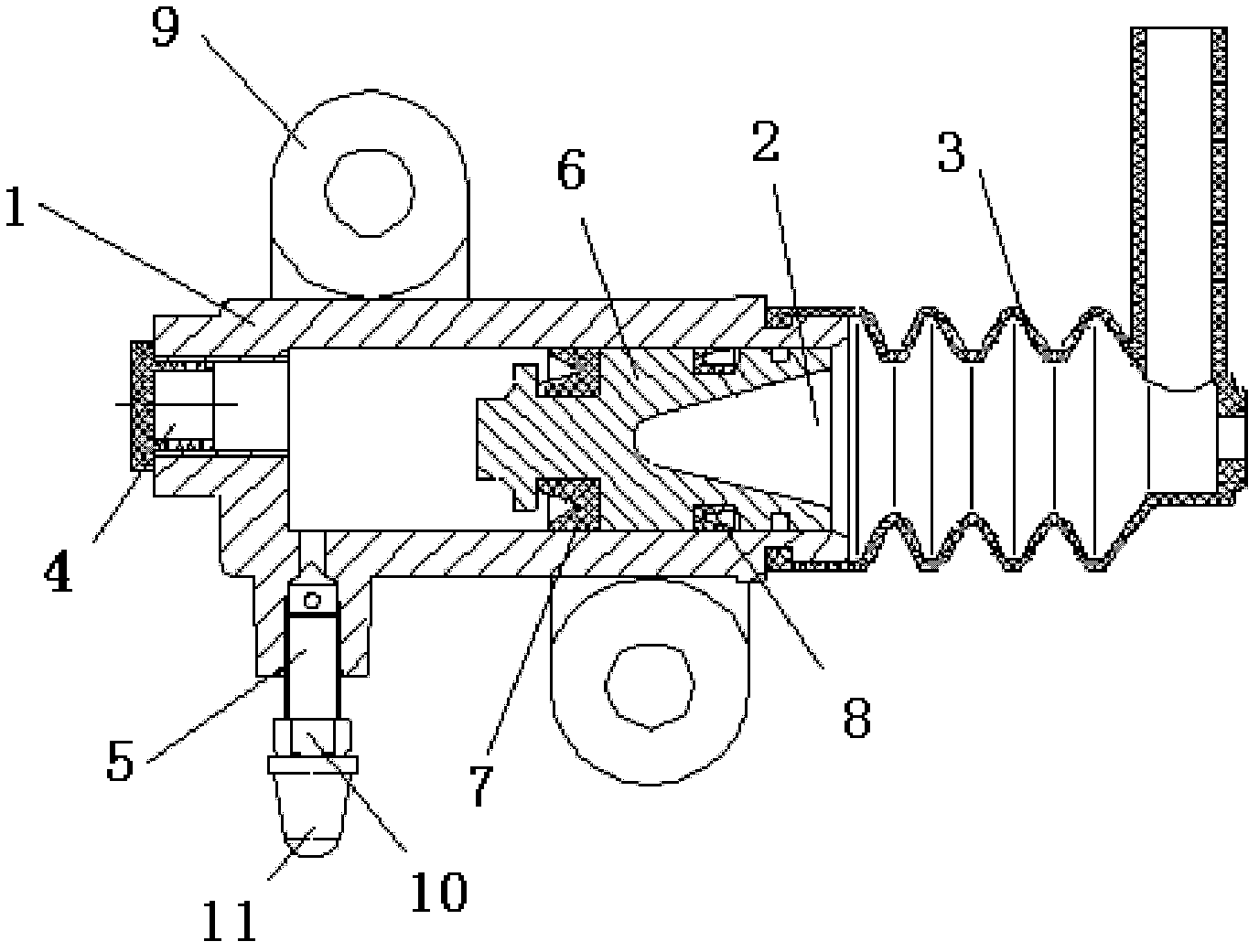
[0009] Referring to the accompanying drawings, a clutch slave cylinder includes a housing 1, the right end of the housing 1 is provided with an opening 2, and a dust cover 3 is fixedly installed on the side wall of the opening 2, and the left end of the housing 1 An oil inlet 4 is provided, an exhaust port 5 communicates with the side wall of the housing 1, a piston 6 is slidably installed inside the housing 1, and main aprons are arranged at intervals on the side wall of the piston 6 7 and the auxiliary apron 8, the side wall of the housing 1 is provided with a mounting seat 9, the exhaust port 5 is screwed with a deflation screw 10, and the deflation screw 10 is covered with a deflation cap 11 .
Login to View More PUM
 Abstract
The invention discloses a minute pump for a clutch. The minute pump comprises a shell; the right end of the shell is provided with an opening; the side wall of the opening end is fixedly provided with a dust cover; the left end of the shell is provided with an oil inlet; the side wall of the shell is communicated with an air exhaust port; a piston is arranged in the shell in a sliding way; main leather collars and auxiliary leather collars are arranged on the side wall of the piston at intervals; the side wall of the shell is provided with an installation seat; a bleed screw is screwed on the air exhaust port; and a bleed cap is covered on the bleed screw. The minute pump has a simple and compact structure and a small volume and can effectively prevent dust and oil leakage.
Description
technical field [0001] The invention relates to a clutch cylinder. Background technique [0002] The clutch in the current automobile operating mechanism uses a conventional clutch cylinder, and only one sealing ring is arranged between the piston in the structure and the inner wall of the housing, which is prone to oil leakage during the work process. In addition, the existing piston In the connection structure with the push rod, after the gap produced by the wear of the clutch plate, it cannot be automatically replenished. The disadvantage of this system is that the structure is complex. The pump produces eccentric wear, which affects the service life of the sub-pump. Contents of the invention [0003] The present invention provides a clutch sub-cylinder assembly which is simple in structure, compact in size and small in size, and can effectively prevent dust ingress and oil leakage, aiming at the problem of oil leakage during the working process of the above-mentione...
Claims
Login to View More Application Information
Patent Timeline
 IPC IPC(8): F16D48/02
Inventor周建
Owner芜湖博格汽车零部件有限公司