Built-in infrared touch screen

An infrared touch screen, built-in technology, applied in the direction of instruments, electrical digital data processing, data processing input/output process, etc., can solve the problems of circuit board warping, easy warping, circuit board deformation, etc., to achieve Ensure flatness, reduce thickness and enhance strength

Active Publication Date: 2012-04-25
BEIJING IRTOUCH SYST CO LTD
View PDF9 Cites 0 Cited by
  • Summary
  • Abstract
  • Description
  • Claims
  • Application Information

AI Technical Summary

Problems solved by technology

[0003] The infrared touch screen in the prior art generally installs the printed circuit board equipped with the infrared pair tube array in a frame, and leaves space for placing the infrared pair tube array and other electronic devices in the frame, and utilizes the strength of the frame and flatness to maintain the strength and flatness of the circuit board, but because there is a gap between the frame and at least one side of the circuit board, the circuit board is easily deformed, even if it is pressed with foam, it is only a local point-to-point contact , prone to warping
For example, the patent No. is CN200620063264.2 and the patent No. is CN200720190699.8 Chinese patent application disclosed content, these two patents all leave a cavity inside the frame, used for infrared emission tube, infrared receiving tube and other The electronic components are avoided. On the one hand, the touch screen with this structure increases the thickness of the infrared touch screen. If the infrared touch screen with this structure is installed inside the display, it is difficult to make the display very thin; The circuit board in the cavity is also prone to warping and deformation, which will affect the performance of the infrared touch screen in severe cases

Method used


Image

  • Built-in infrared touch screen
  • Built-in infrared touch screen
  • Built-in infrared touch screen

Examples


Embodiment Construction

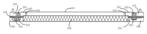
[0028] In this specification, for the convenience of description, in the state after the infrared touch screen is assembled, the state is observed from the front, and the side on which the infrared emitting tube or the infrared receiving tube is installed on the printed circuit board is called the upper surface of the printed circuit board, and the other side is called the upper surface of the printed circuit board. One side is called the lower surface of the printed circuit board, the support above the printed circuit board is called the upper support, and the support below the printed circuit board is called the lower support.

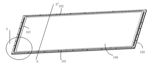
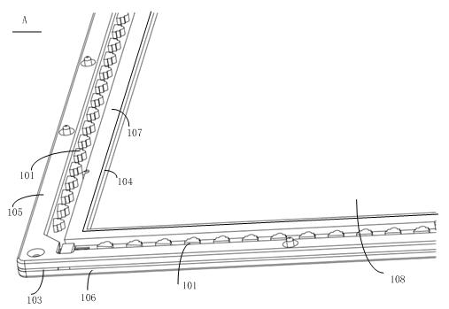
[0029] Attached below Figure 1 to Figure 7 The specific structure of the built-in infrared touch screen in the first embodiment of the present invention will be described in detail.

[0030] exist figure 1 , Figures 2 to 3 The built-in infrared touch screen of the first embodiment of the present invention shown in the figure includes an infrared ...


PUM


Abstract

The invention provides a built-in infrared touch screen, relates to the field of structure manufacture of infrared touch screens, and is designed to lower the thickness of the infrared touch screen. The built-in infrared touch screen comprises a touch panel, a printed circuit board on which an infrared emission tube and an infrared receiving tube are arranged, an upper support piece arranged on the printed circuit board, a lower support piece arranged under the printed circuit board, and a photic sheet arranged in front of the infrared emission tube or infrared receiving tube. The built-in infrared touch screen is characterized in that a clearance hole and / or clearance slot which are / is matched with an electronic device at the lower surface of the printed circuit board and used for keeping a clearance for the electronic device are / is arranged on the lower support piece, and the upper support piece, the printed circuit board and the lower support piece are mutually clamped and connected. The built-in infrared touch screen provided by the invention is applicable to touch displays and can be used for lowering the thickness of the displays.

Description

technical field [0001] The invention relates to the field of infrared touch screens, in particular to an ultra-thin infrared touch screen with a built-in structure. Background technique [0002] The existing infrared touch screen generally consists of an array of infrared tubes installed on a printed circuit board around the touch detection area. , so that the infrared receiving tube can receive the infrared light emitted by the corresponding infrared emitting tube. When there is a touch object in the touch detection area, the light between the infrared emitting tube or the infrared receiving tube is blocked by the touching object, and the infrared receiving tube cannot receive the infrared light emitted by the infrared emitting tube. According to the infrared receiving tube that cannot receive infrared light The position information of the touch object can be determined. [0003] The infrared touch screen in the prior art generally installs the printed circuit board equip...

Claims


Application Information

Patent Timeline
IPC IPC(8): G06F3/044
Inventor 尚晓东吴羊群刘新斌刘建军叶新林
Owner BEIJING IRTOUCH SYST CO LTD
Why Eureka
Try Eureka