Interlocking device of draw-out circuit breaker

A technology of interlocking device and circuit breaker, which is applied in the direction of switchgear, pull-out switchgear, electrical components, etc., can solve problems such as stuck, unprotected, unfavorable for manufacturing, installation and maintenance, and eliminate assembly errors , The overall structure is concise and the effect of ensuring reliability

Active Publication Date: 2012-10-10
CHANGSHU SWITCHGEAR MFG CO LTD (FORMER CHANGSHU SWITCHGEAR PLANT)
View PDF5 Cites 5 Cited by
  • Summary
  • Abstract
  • Description
  • Claims
  • Application Information

AI Technical Summary

Problems solved by technology

[0006] However, the above-mentioned CN1041468C shows that the push rod is easy to deviate from the position or The lack of breaking is pointed out by the utility model patent authorization announcement number CN200953291Y (interlocking device for drawer-type plastic case circuit breaker) and made up for by the technical solution provided by CN200953291Y
[0007] However, the above two patent schemes still have the following disadvantages: one, because the interlocking device is separately installed on two independent parts, so due to assembly Errors have a certain impact on the reliability of the interlock mechanism. For example, CN1041468C installs the cam on the fixed part, that is, the socket, and installs the bracket equipped with transmission rods and rockers on the rear plate of the circuit breaker. CN200953291Y installs the cam on the fixed part, that is, the socket, and installs the side mechanism on the side of the circuit breaker contact module; second, because the entire interlock mechanism is open, it cannot be effectively shielded, so when it is subjected to dust After the attack, the interlock mechanism exposed in the air may be stuck or even stuck; third, it is not universal, for example, the same interlock mechanism cannot be used for circuit breakers with different rated current specifications; fourth, zero There are many parts and the overall structure is complex, which is not conducive to manufacturing, installation and maintenance

Method used


Image

  • Interlocking device of draw-out circuit breaker
  • Interlocking device of draw-out circuit breaker
  • Interlocking device of draw-out circuit breaker

Examples


Embodiment Construction

[0026] In order to enable the examiners of the patent office, especially the public, to understand the technical essence and beneficial effects of the present invention more clearly, the applicant will describe in detail the following in the form of examples, but none of the descriptions to the examples is an explanation of the solutions of the present invention. Any equivalent transformation made according to the concept of the present invention which is merely formal but not substantive shall be regarded as the scope of the technical solution of the present invention.

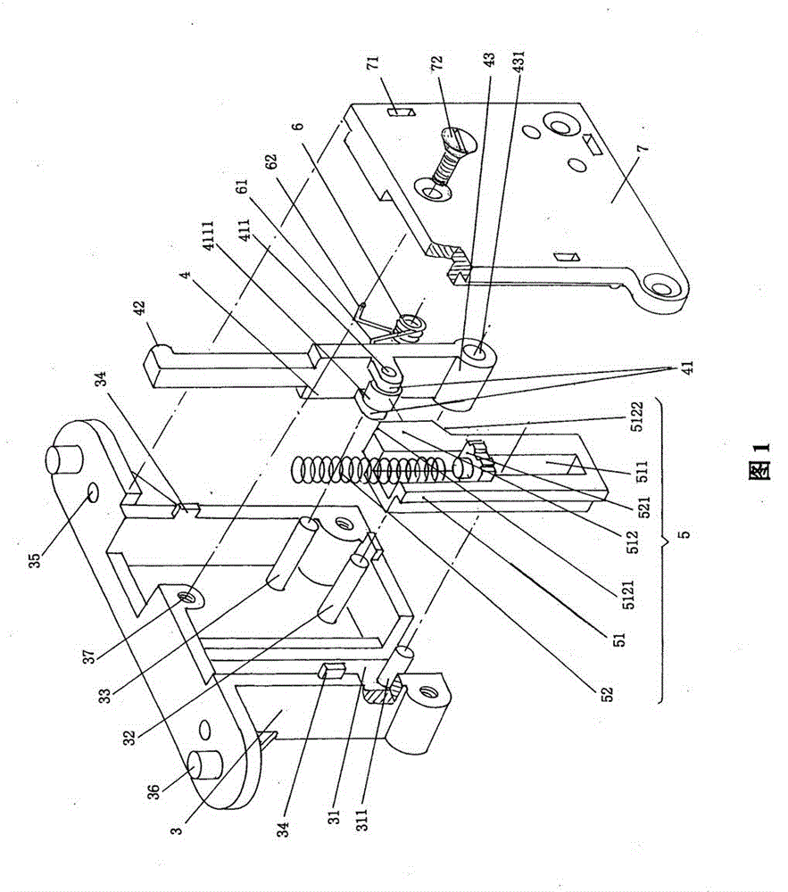
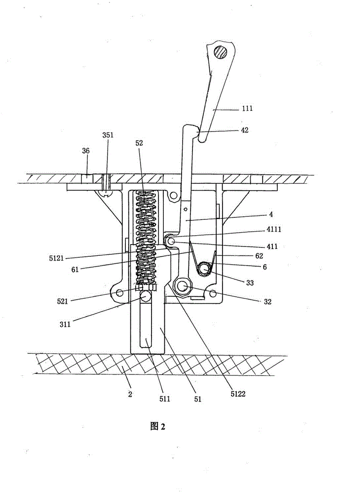
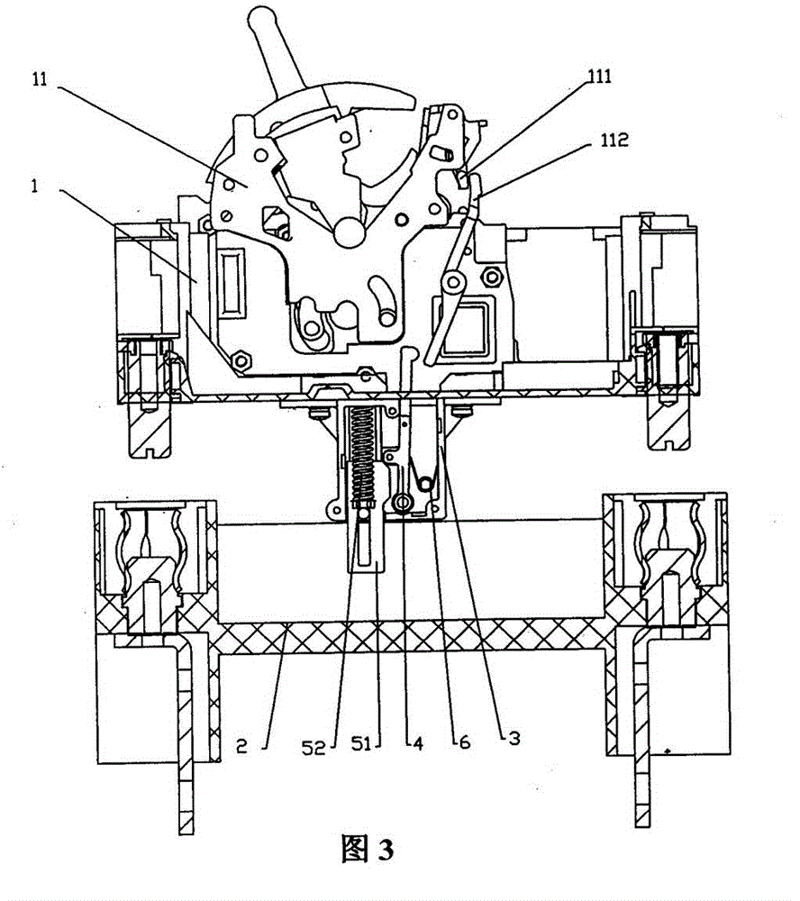
[0027] please see figure 1 and figure 2 and combine Figure 3 to Figure 5 ,exist Figure 2 to Figure 5 The figure shows the circuit breaker body 1 as the movable part of the withdrawable circuit breaker and the socket 2 as the fixed part of the withdrawable circuit breaker. According to the known technology, the circuit breaker body 1 has an operating mechanism 11, and the operating mechanism 11 ha...


PUM


Abstract

The invention relates to an interlocking device of a draw-out circuit breaker, and belongs to the field of electrical techniques. The draw-out circuit breaker comprises a circuit breaker body and a socket. The circuit breaker body comprises an operating mechanism with a trip lever and a transmission rod. The interlocking device comprises a base, a rotating pushrod, a rotating pushrod actuating device and a rotating pushrod return spring, wherein the rotating pushrod is arranged on the base, and one end of the rotating pushrod which faces to the operating mechanism stretches out of the base, extends into the circuit breaker body and corresponds to the transmission rod; and the rotating pushrod actuating device is assembled on the base, one side of the rotating pushrod actuating device corresponding to the rotating pushrod is in contact with the rotating pushrod, and the part of the rotating pushrod actuating device which faces to the socket stretches out of the base and corresponds to the socket; and one end of the rotating pushrod return spring is born on the rotating pushrod and the other end of the rotating pushrod return spring is born on the base. The interlocking device of the draw-out circuit breaker has the advantages that the assembling errors caused by separate installation are eliminated and the action reliability is ensured; the invasion of dust and foreign matters is avoided; the interlocking device is universally suitable for draw-out circuit breakers at different current ratings; and since the overall structure is simple, the manufacturing, installation and maintenance are facilitated.

Description

technical field [0001] The invention belongs to the field of electrical technology, and in particular relates to an interlock device of a withdrawable circuit breaker. Background technique [0002] The withdrawable and plastic case circuit breaker operates in a plug-and-pull manner to connect or separate the circuit breaker body as a movable part and the socket as a fixed part, which brings great convenience to users for use and maintenance. [0003] Considering the safety of the operator, and in accordance with the relevant national standards, the drawer mechanism should be equipped with an interlock device that allows the isolation contacts to be separated or reclosed only after the main contacts of the circuit breaker are disconnected. That is to say, it is not allowed to pull out or insert the movable part (that is, the circuit breaker body) relative to the fixed part (that is, the socket) when the main contact of the circuit breaker is in the energized state. [0004] ...

Claims


Application Information

Patent Timeline
Patent Type & Authority Patents(China)
IPC IPC(8): H02B11/133
Inventor 晏卫江黄剑陈志刚王炯华管瑞良
Owner CHANGSHU SWITCHGEAR MFG CO LTD (FORMER CHANGSHU SWITCHGEAR PLANT)
Why Eureka
Try Eureka