Mould for tubing material forming

A mold and pipe technology, applied in the field of pipe forming molds, can solve the problems of difficult to guarantee product dimensional accuracy and shape accuracy, complicated operation and operation of process methods, complicated mold debugging, etc., to achieve simple debugging, easy mold manufacturing, and low manufacturing costs. Effect

Active Publication Date: 2012-05-02
隆昌山川机械有限责任公司
View PDF5 Cites 14 Cited by
  • Summary
  • Abstract
  • Description
  • Claims
  • Application Information

AI Technical Summary

Problems solved by technology

[0005] The purpose of the present invention is to provide a mold for pipe forming, which solves the technical problems of complex operation of the existing pipe mold, difficulty in ensuring product size accuracy and shape accuracy, complicated mold debugging, and high manufacturing cost, so as to effectively to solve the problems in the above-mentioned prior art

Method used


Image

  • Mould for tubing material forming
  • Mould for tubing material forming
  • Mould for tubing material forming

Examples


Embodiment

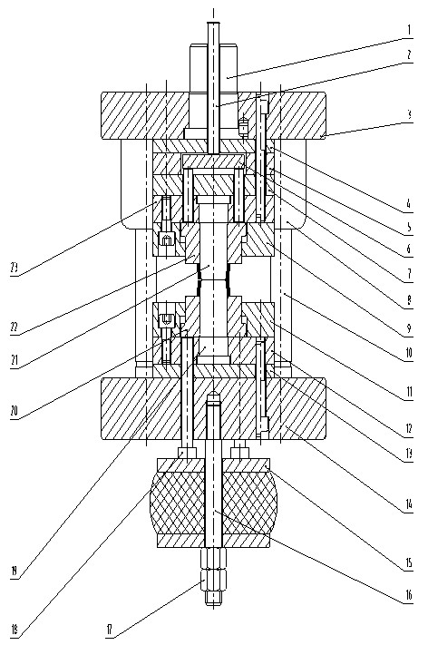
[0032] like figure 1 As shown, the pipe forming mold of the present invention includes an upper mold part, a lower mold part and a guide part.

[0033] The upper mold part includes a mold handle 1, a punching rod 2, an upper mold base 3, a backing plate 4, a hollow backing plate 5, a hitting plate 6, an upper backing plate 7, an upper cover plate 9, an upper punch 21, and an upper top block 22 and the upper fixed plate 23, the backing plate 4 is located under the upper die base 3; the hollow backing plate 5 is located under the backing plate 4, the upper backing plate 7 is located under the hollow backing plate 5, and the upper fixing plate 23 is located on Below the upper backing plate 7, the upper cover plate 9 is arranged under the upper fixing plate 23, and the backing plate 4, the hollow backing plate 5, the upper backing plate 7 and the upper fixing plate 23 are respectively threadedly connected with the upper mold base 3 to become one . The upper jacking block 22 is s...


PUM


Abstract

The invention discloses a mould for tubing material forming, comprising an upper mould part, a lower mould part and a guide part, wherein the upper mould part comprises a mould handle, a knocking rod, an upper mould seat, an upper cushion plate, an upper cover plate, an upper convex mould, an upper top block and an upper fixed plate; the upper top block is sleeved in the upper cover plate; the upper convex mould passes through the upper top block; the top of the upper convex mould is in contact with the upper cushion plate; the upper convex mould is in sliding fit with the upper top block; the lower mould part comprises a lower cover plate, a lower fixed plate, a lower cushion plate, a lower mould seat, a lower convex mould and a lower top block; the lower top block is sleeved in the lower cover plate; the lower convex mould passes through the lower top block; the bottom of the lower convex mould is in contact with the lower cushion plate; the lower convex mould is in sliding fit with the lower top block; the guide part comprises a guide sleeve and a guide column; the guide sleeve penetrates in the upper mould seat; and the guide column penetrates in the lower mould seat. The mould uses the upper and lower convex moulds to press parts, so that the tubing materials are deformed to necessary shapes; the lengths of products are controlled by the upper and lower top blocks, the sizes of the two ends of each product are ensured to be consistent, the quality requirements of products are ensured, and the material pushing operation is convenient.

Description

technical field [0001] The invention relates to a mold for pipe forming, which belongs to the technical field of molds. [0002] Background technique [0003] Among the stamping products, some products are directly formed by pipes, such as the suspension rings that play a connecting role in vehicle shock absorbers. This type of parts requires the consistency of the inner hole, length dimension and both ends of the stamping process. , because there are many sizes and shapes that need to be controlled, and the error of the dimensions at both ends is required to be less than 0.2mm. In addition, due to the particularity of the pipe, it is difficult to locate during the forming, the operation is complicated during the process, the labor intensity of the operator is high, and the processing The dimensional accuracy and shape accuracy of the produced products are difficult to guarantee, the mold debugging is complicated, and the manufacturing cost is high. Therefore, it is not eas...

Claims


Application Information

Patent Timeline
Patent Type & Authority Applications(China)
IPC IPC(8): B21D37/10
Inventor 吴家文胡宏
Owner 隆昌山川机械有限责任公司
Why Eureka
Try Eureka