Casting bonding method for hollow fiber membrane assembly

A fiber membrane and hollow technology, applied in the field of hollow fiber membrane modules, can solve the problems of incomplete bonding, weak bonding force between interfaces, increase interface bonding, etc., achieve reduced volume shrinkage, low cost, and overcome spinning Effect

CN102431170BActive Publication Date: 2013-09-04JIANGSU SUJING GROUP +1
7 Cites 0 Cited by

Patent Information

Authority / Receiving Office
CN · China
Patent Type
Patents(China)
Current Assignee / Owner
Publication Date
2013-09-04

Smart Images

  • Figure 1
    Figure 1
  • Figure 2
    Figure 2
Patent Text Reader

Abstract

The invention relates to a casting bonding method for a hollow fiber membrane assembly. The method comprises the following steps: 1, adding an inorganic enhancement material to an enpoxy resin or a polyurethane resin which is used as a binder before casting, wherein the weight of the inorganic enhancement material accounts for 2-4% of the weight of the binder; 2, uniformly mixing them; and 3, casting. The inorganic enhancement material comprises 1-5 wt% of organic particles of equal to or greater than 50 meshes and equal to or less than 60 meshes, 10-30 wt% of organic particles of equal to or greater than 60 meshes and equal to or less than 80 meshes, 50-70 wt% of organic particles of equal to or greater than 80 meshes and equal to or less than 120 meshes, 10-30 wt% of organic particles of equal to or greater than 120 meshes and equal to or less than 200 meshes, and 1-5 wt% of organic particles of equal to or greater than 200 meshes. The method of the invention has the advantages of overcome of problems of silk drawing and shelling appearing in the use process, membrane assembly service life improvement, simple technology and low cost.
Need to check novelty before this filing date? Find Prior Art

Description

technical field

[0001] The present invention relates to a method of using epoxy resin or polyurethane resin to bond hollow fiber membrane filaments and external structural parts by centrifugal or static casting to form a hollow fiber membrane module. Background technique

[0002] Membrane module is the core of membrane technology. The structure of membrane module plays a decisive role in the membrane separation process. Now the general membrane module uses epoxy resin or polyurethane resin to cast and bond the hollow fiber membrane filament and the outer structure. Together, but because the hollow fiber membrane, epoxy resin or polyurethane resin, and the outer structural parts are all polymer materials, the bonding force between the interfaces is not strong, and because the epoxy resin or polyurethane resin is solidified during casting During the process, there is volume shrinkage, which makes the epoxy resin or polyurethane resin and the outer structural parts unable to be...

Examples

Embodiment 1~4

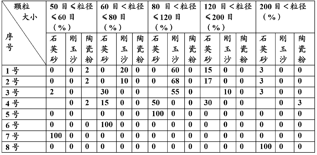
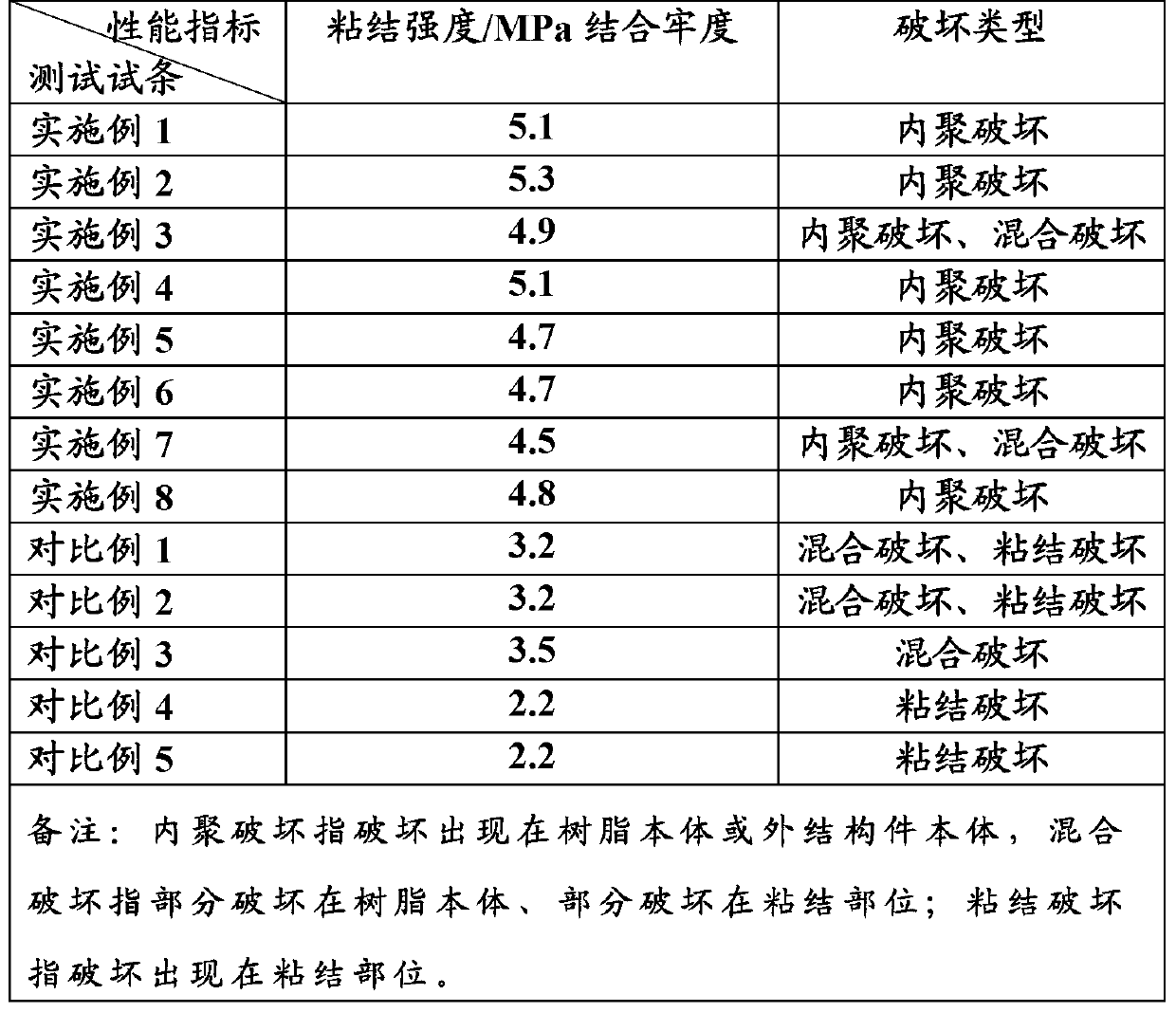
[0018] Add No. 1 to No. 4 inorganic reinforcing materials in Table 1 to the epoxy resin binder (618 epoxy resin, 105 curing agent), the addition amount is 3% of the weight of the epoxy resin binder, and stir The method is used to make the resin and the inorganic reinforcing material evenly mixed, and it is added to the casting part when casting the hollow fiber membrane module. The conventional process is used for casting. After the casting is completed, the bonding fastness between the hollow fiber membrane and the outer member is tested. The damage results are shown in Table 2.

Embodiment 5~8

[0020] Add No. 1 to No. 4 inorganic reinforcing materials in Table 1 to the polyurethane resin binder (Korean Easy Tech Company, EPU-3000), the addition amount is 3% of the weight of the polyurethane resin binder, and the method is stirred Mix the resin and the inorganic reinforcing material evenly, and add it to the casting part when casting the hollow fiber membrane module. The conventional process is used for casting. After the casting is completed, the bonding fastness between the hollow fiber membrane and the outer member is tested. The damage results are shown in Table 2.