
Booster with emergency braking function

A technology of emergency braking and booster, applied in the directions of brakes, brake transmissions, transportation and packaging, etc., can solve the problems of rapid pressing and potential safety hazards, and achieve improved braking force, low cost, and simple component structure. Effect

Inactive Publication Date: 2014-05-07
GUANGZHOU ZHONGBO BRAKE SYST CO LTD
View PDF5 Cites 0 Cited by
  • Summary
  • Abstract
  • Description
  • Claims
  • Application Information

AI Technical Summary

Problems solved by technology

[0004] However, there is a problem in the above-mentioned technical solution, which is that the force required for the angular displacement of the lever is relatively large. For weak or female drivers, it is difficult to achieve it quickly by pressing the pedal in an instant, so it is still impossible to move the lever in an emergency. When the situation occurs, quickly brake the vehicle, and there are still potential safety hazards

Method used


Image

  • Booster with emergency braking function
  • Booster with emergency braking function
  • Booster with emergency braking function

Examples


Embodiment 1

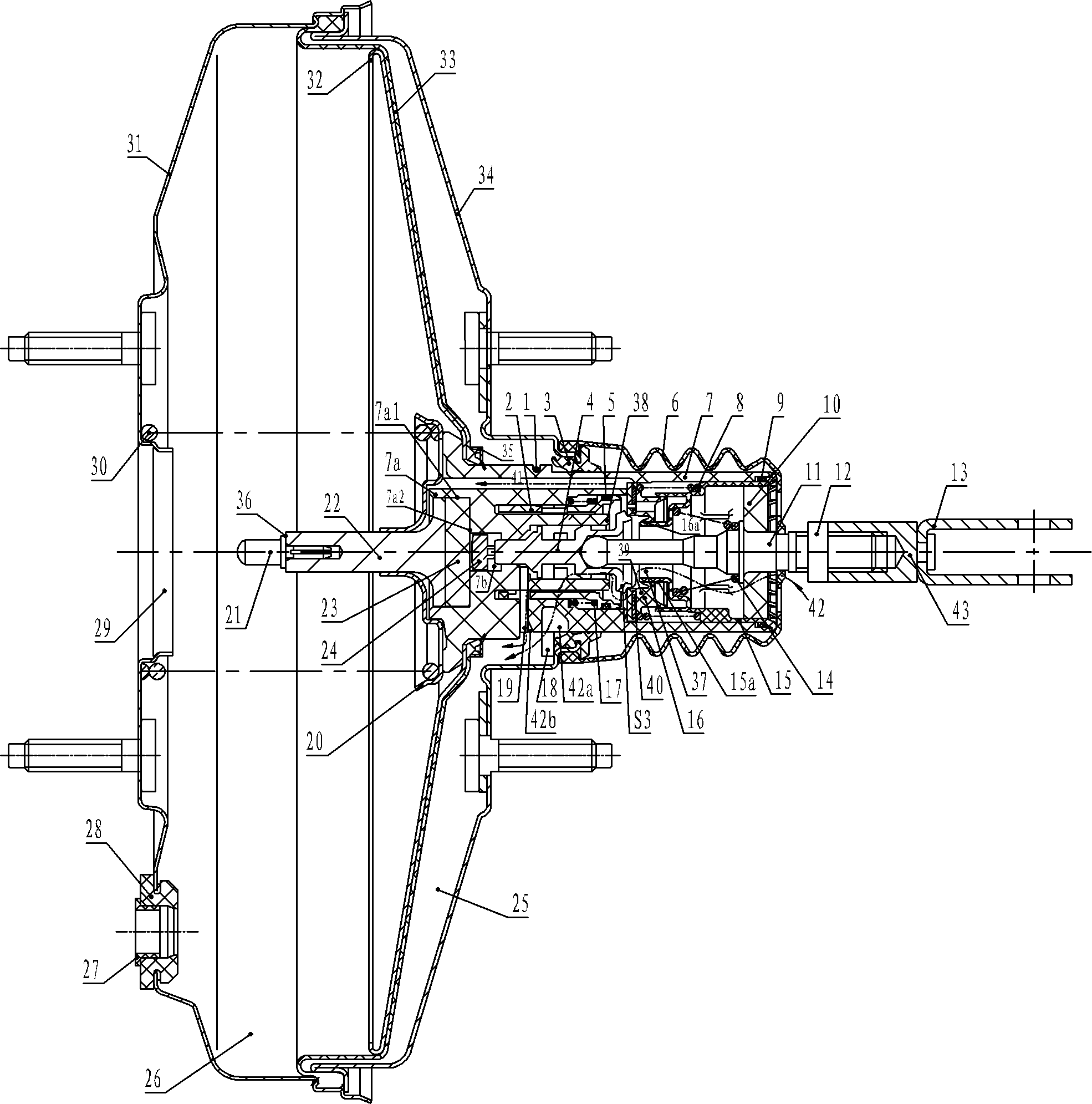
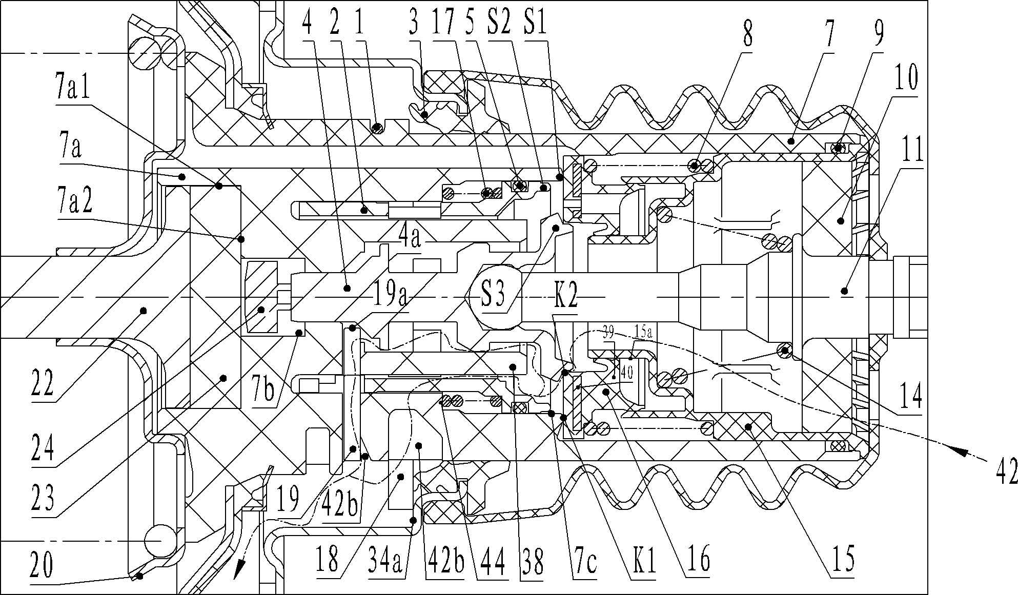
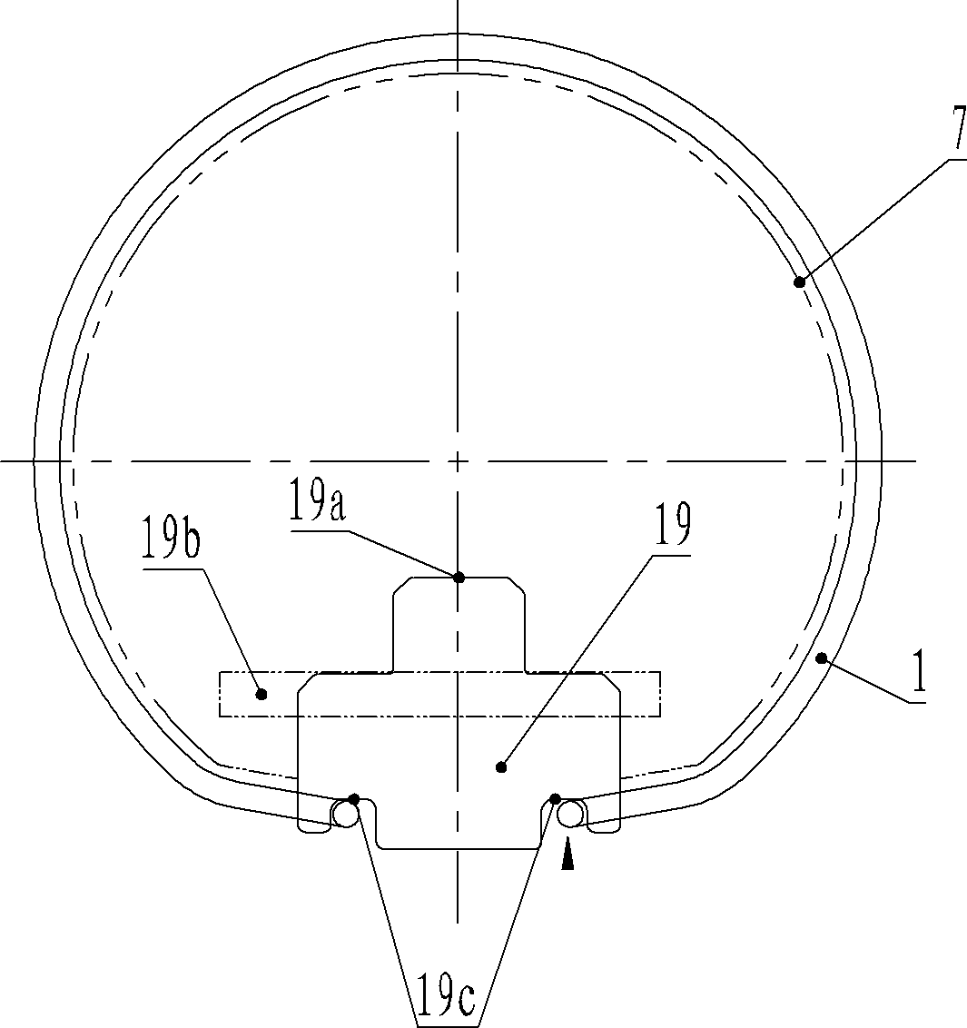
[0031] Such as figure 1 , figure 2 As shown, a booster with an emergency braking function includes a rear shell 34 and a front shell 31, and a piston housing 7 is slidably installed in the rear shell. An annular rear housing sealing ring 3 is installed at the rear housing mouth, so that the piston casing periphery and the rear housing 34 form a seal. It also includes a diaphragm 33 whose outer edge is tightly sealed to the housing, a diaphragm 32 that cooperates with the diaphragm 33, the diaphragm 32 and the diaphragm 33 are connected to the outer periphery of the piston housing 7, and the diaphragm, diaphragm 33 are connected by the locking plate 35 The diaphragm is riveted and fixed on the piston casing, and the piston casing, diaphragm 32 and diaphragm 33 divide the interior of the booster into front and rear chambers, the front chamber is a vacuum chamber 26, and the rear chamber is an atmospheric chamber 25; the front housing 31 is riveted and sealed with the rear she...


PUM


Abstract

The invention provides a booster with an emergency braking function, which belongs to the technical field of automotive vacuum braking boosters. By means of a slider and a sliding sleeve, not only normal braking effect can be achieved, but also braking force can be increased greatly with smaller pedal force by quickly pressing down a brake pedal at a certain maintained speed to lead the openness of an atmosphere valve to be larger than that in the normal braking process, and thereby a vehicle can acquire maximum braking deceleration in a short time, and quicker braking than a normal booster can be achieved. The technology of the booster with the emergency braking function can be widely applied to automotive braking boosters.

Description

technical field [0001] The invention relates to a vacuum booster for automobile braking, in particular to a vacuum booster with emergency braking function. Background technique [0002] A vacuum booster is a vacuum-assisted servo that works in conjunction with your car's brakes. Its working principle is that when the brake pedal is stepped on, the input rod is pushed to move the valve piston forward, so that the atmospheric valve seat is separated from the atmospheric valve, allowing the atmospheric air to enter the atmospheric chamber from the outside, and the piston due to the pressure difference between the vacuum chamber and the atmospheric chamber Moving forward, pushes the master cylinder piston, thereby generating output force in the master cylinder to brake the car. In the traditional vacuum booster, the booster linearly amplifies the input force according to a certain ratio, so when an emergency occurs, the traditional booster cannot obtain a large braking force in...

Claims


Application Information

Patent Timeline
Patent Type & Authority Patents(China)
IPC IPC(8): B60T13/56
Inventor 魏红涛
Owner GUANGZHOU ZHONGBO BRAKE SYST CO LTD
Learn More