Hooped steel reinforced concrete beam-column joint of core area U-shaped column

A technology of beam-column joints and concrete, which is applied in the direction of architecture and building construction, can solve the problems of component fabrication and construction inconvenience, and achieve the effect of saving construction period and reducing construction cost

Active Publication Date: 2012-05-02
中国建筑东北设计研究院有限公司
View PDF5 Cites 19 Cited by
  • Summary
  • Abstract
  • Description
  • Claims
  • Application Information

AI Technical Summary

Problems solved by technology

[0006] The object of the present invention is to provide a steel concrete beam-column joint with U-shaped column stirrups in the core area, which solves the problem of opening holes on the web of the steel beam in order to allow the column st...

Method used


Image

  • Hooped steel reinforced concrete beam-column joint of core area U-shaped column
  • Hooped steel reinforced concrete beam-column joint of core area U-shaped column
  • Hooped steel reinforced concrete beam-column joint of core area U-shaped column

Examples


Embodiment Construction

[0017] The present invention will be described in detail below in conjunction with the accompanying drawings.

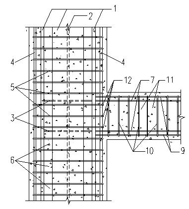
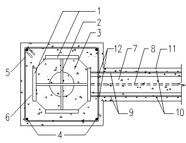
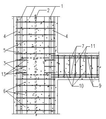
[0018] The invention solves the problem of inconvenience caused to component manufacture and construction by opening holes on the web plate of the shaped steel beam in order to allow the column stirrup to pass through the traditional shaped steel concrete beam-column joint. The steel concrete beam-column joint with U-shaped column stirrups in the core area is a special form of the beam-column joint of the steel concrete structure. The core area of ​​the joint uses U-shaped stirrups 13 instead of the original closed stirrups 5, see attached image 3 -4. At the same time, there is no need to open column stirrup through holes 12 on the beam-shaped steel web, and it is suitable as a structural form of beam-column joints of high-rise and super high-rise buildings.

[0019] The present invention as image 3 As shown in -4, it consists of column-shaped steel flange plate ...


PUM


Abstract

The invention provides a hooped steel reinforced concrete beam-column joint of a core area U-shaped column, which relates to the field of constructional engineering. The hooped steel reinforced concrete beam-column joint of the core area U-shaped column comprises a column type steel flange plate, a column type steel web plate, a column horizontal stiffened steel plate, a column longitudinal bar, a column hoop, a column U-shaped hoop and a column concrete as well as a beam type steel flange plate, a beam type steel web plate, a beam longitudinal bar, a beam hoop and beam concrete; the beam-column joint core area is steel reinforced concrete structure building or structure of the U-shaped hoop. In the joint core area, the original closed hoop is replaced with the U-shaped hoop which is suitable for the structural forms at the beam-column joints of high-rise and super high-rise buildings. According to the invention, a column hoop through hole which is formed on the beam type steel web plate due to the need of enabling the column hoop to penetrate through the beam type steel web plate in the common steel reinforced concrete beam-column joint is avoided; one procedure is reduced in the member manufacturing process; the trouble of first penetrating through the reinforcing steel bar for making the hoop and then carrying out bending molding and segmental welding on the reinforcing steel bar during construction is prevented; and the beam-column joint can be manufactured in advance so that the construction period is shortened and the construction costs are saved.

Description

technical field [0001] The invention relates to the field of construction engineering, in particular to a U-shaped column stirrup steel concrete beam-column node in the core area. Background technique [0002] Steel-reinforced concrete structure (or steel-reinforced concrete structure) is composed of hot-rolled or welded steel, bound longitudinal reinforcement and horizontal stirrups, and poured concrete. In recent years, due to the advantages of both steel structure and concrete structure, the steel-concrete structure has high bearing capacity, good seismic performance, and can reduce project cost, shorten construction period, and save materials, etc., it is more and more widely used in high-rise and superstructure Among high-rise buildings. [0003] In my country's "Technical Regulations for Steel-reinforced Concrete Composite Structures" (JGJ 138-2001) and "Technical Regulations for Steel-reinforced Concrete Structures" (YB 9082-2006), the beam-column joints consist of ...

Claims


Application Information

Patent Timeline
IPC IPC(8): E04B1/58
Inventor 陈勇
Owner 中国建筑东北设计研究院有限公司
Why Eureka
Try Eureka