Liquid piston hydraulic-pneumatic engine

A liquid piston and engine technology, applied in the field of liquid piston liquid-gas engines, can solve the problems of large volume, small expansion space, occupying volume and weight, and achieve the effect of small volume, light weight and high efficiency

Inactive Publication Date: 2012-05-02
ZEROQ SCI & TECH
View PDF5 Cites 1 Cited by
  • Summary
  • Abstract
  • Description
  • Claims
  • Application Information

AI Technical Summary

Problems solved by technology

[0002] Research on using liquefied gas, such as liquid nitrogen, to manufacture engines is becoming more and more active. However, due to the relatively low pressure of the gas produced by liquefied gas, a large expansion space is required. However, the traditional crank-link mechanism has a large volume and a small expansion space. Most of the volume and weight is taken up by the crank linkage

Method used


Image

  • Liquid piston hydraulic-pneumatic engine
  • Liquid piston hydraulic-pneumatic engine
  • Liquid piston hydraulic-pneumatic engine

Examples


Embodiment 1

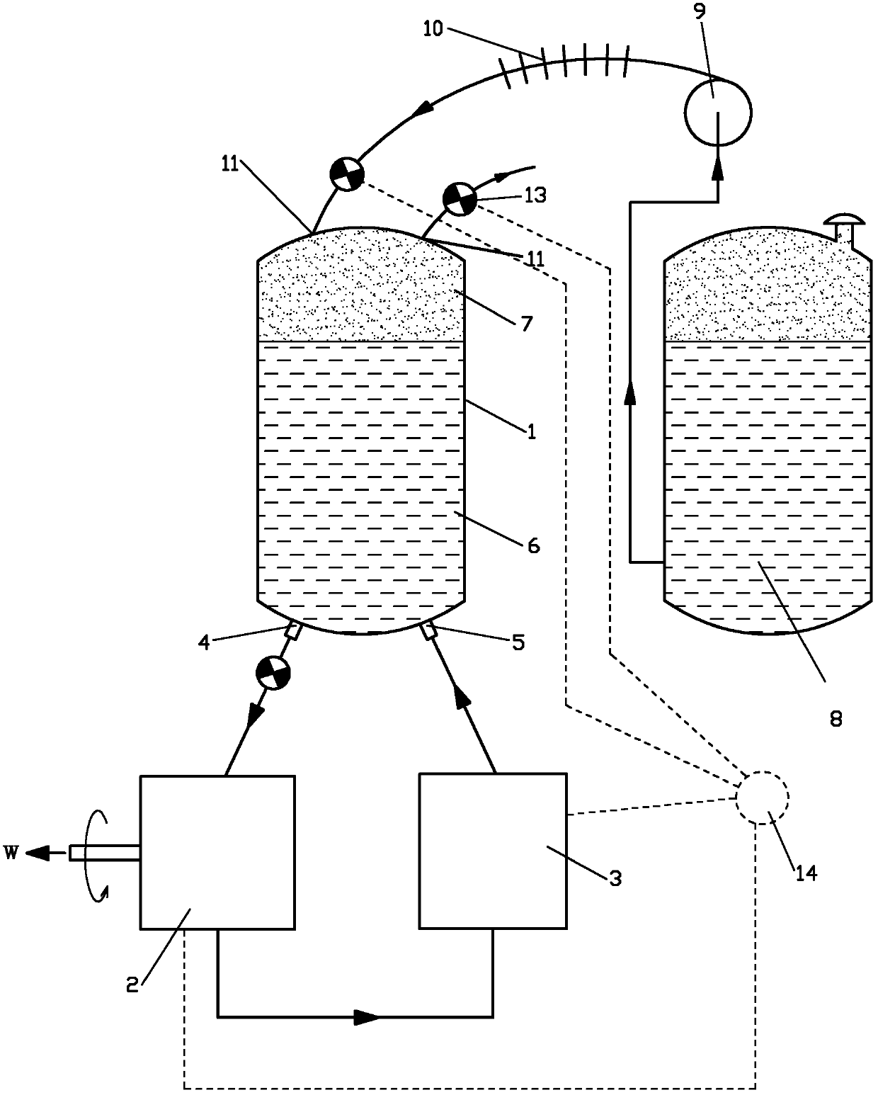
[0037] like figure 1 The liquid-piston liquid-pneumatic engine shown includes a gas-liquid cylinder 1, a hydraulic power mechanism 2, a liquid working medium return system 3 and a liquid gas source 8, and the liquid gas source 8 passes through a high-pressure liquid pump 9, liquid heat absorption and heat exchange successively. The device 10 communicates with the gas-liquid cylinder 1, and the liquid in the liquid gas source 8 is quantitatively introduced into the liquid heat-absorbing heat exchanger 10 and gasified in the liquid heat-absorbing heat exchanger 10 to form a gas work The gas working fluid 7 communicates with the gas-liquid cylinder 1 through the gas working fluid control valve 12 .

[0038]An exhaust port 11 is arranged on the gas-liquid cylinder 1, an exhaust control valve 13 is arranged at the exhaust port 11, a liquid working medium outlet 4 and a liquid working medium return port 5 are arranged on the gas-liquid cylinder 1, The liquid working medium outlet ...

Embodiment 2

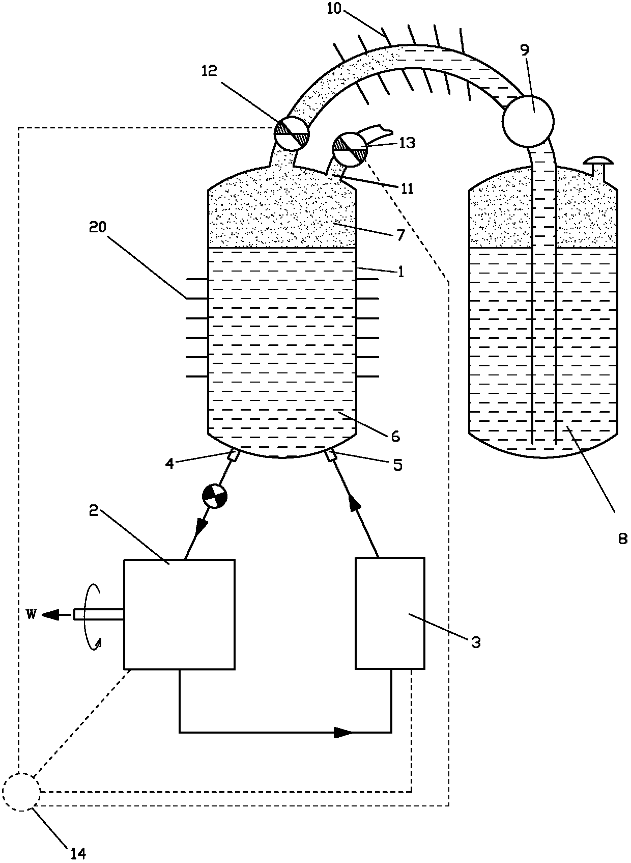
[0042] like figure 2 The difference between the shown liquid-piston liquid-gas engine and Embodiment 1 is that a gas-liquid cylinder working medium heat-absorbing heat exchanger 20 is arranged on the gas-liquid cylinder 1 .

Embodiment 3

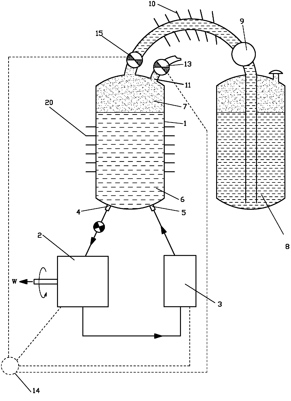
[0044] like image 3 The difference between the liquid-piston liquid-pneumatic engine shown in Embodiment 1 is that it includes a gas-liquid cylinder 1, a hydraulic power mechanism 2, a liquid working medium return system 3 and a liquid gas source 8, and the liquid gas source 8 passes through the The high-pressure liquid pump 9, the liquid heat-absorbing heat exchanger 10, and the liquid working medium control valve 15 are in communication with the gas-liquid cylinder 1, and the liquid in the liquid gas source 8 is quantitatively introduced into the gas-liquid cylinder 1 and released in the gas-liquid cylinder 1. The gas working fluid 7 is formed by gasification in the gas-liquid cylinder 1; a gas-liquid cylinder working fluid heat-absorbing heat exchanger 20 is arranged on the gas-liquid cylinder 1.

[0045] An exhaust port 11 is arranged on the gas-liquid cylinder 1, an exhaust control valve 13 is arranged at the exhaust port 11, a liquid working medium outlet 4 and a liquid...


PUM


Abstract

The invention discloses a liquid piston hydraulic-pneumatic engine which comprises a pneumatic-hydraulic cylinder, a hydraulic power mechanism, a liquid working medium return system and a liquid gas source, wherein the liquid gas source is communicated with the pneumatic-hydraulic cylinder sequentially through a high-pressure liquid pump and a liquid heat absorption heat exchanger; the liquid in the liquid gas source is quantitatively introduced into the liquid heat absorption heat exchanger and is gasified into a gaseous working medium in the liquid heat absorption heat exchanger; the gaseous working medium is communicated with the pneumatic-hydraulic cylinder through a gaseous working medium control valve, or the liquid gas source is communicated with the pneumatic-hydraulic cylinder sequentially through the high-pressure liquid pump and a liquid working medium control valve; and the liquid in the liquid gas source is quantitatively introduced into the pneumatic-hydraulic cylinder and is gasified into a gaseous working medium in the pneumatic-hydraulic cylinder. According to the invention, a piston crank-link mechanism of the engine is omitted; and the engine disclosed by the invention has the advantages of high efficiency, small volume, light weight and the like.

Description

technical field [0001] The invention relates to the field of thermal energy and power, in particular to a liquid-piston liquid-gas engine. Background technique [0002] Research on using liquefied gas, such as liquid nitrogen, to manufacture engines is becoming more and more active. However, due to the relatively low pressure of the gas produced by liquefied gas, a large expansion space is required, while the traditional crank-link mechanism has a large volume and small expansion space. Most of the volume and weight is taken up by the crank linkage. Therefore, need to invent a kind of small in size, light in weight, can utilize the engine of liquefied gas energy more effectively. Contents of the invention [0003] In order to solve the above problems, the technical scheme proposed by the present invention is as follows: [0004] A liquid-piston liquid-gas engine, comprising a gas-liquid cylinder, a hydraulic power mechanism, a liquid working medium return system, and a l...

Claims


Application Information

Patent Timeline
Patent Type & Authority Applications(China)
IPC IPC(8): F03C1/00F03C1/32
CPCY02T10/125Y02T10/12
Inventor 靳北彪
Owner ZEROQ SCI & TECH
Why Eureka
Try Eureka