

Hydraulic cylinder for adjusting axial position of piston and cylinder body through spherical surface
A hydraulic cylinder and piston technology, applied in the field of hydraulic cylinders, can solve the problems of hydraulic cylinder power consumption increase, failure, axis position and movement direction inconsistency, etc., to achieve the effect of reducing power consumption, improving use efficiency and reliability
- Summary
- Abstract
- Description
- Claims
- Application Information
AI Technical Summary
Problems solved by technology
Method used
Image


Examples
Embodiment 1
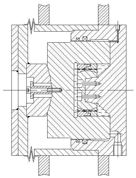
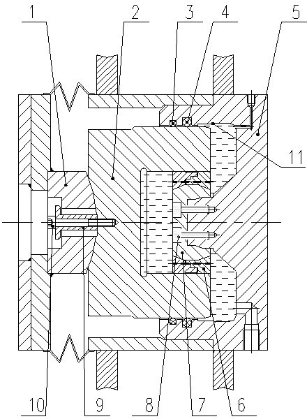
[0015] Embodiment 1: see figure 1 and figure 2 , the specific structure of the present invention is: a hydraulic cylinder that adjusts the axial position of the piston and the cylinder body through a spherical surface, including a piston rod 1, a piston 2 with a "concave" cross section, a second sealing ring 4, and a "concave" cross section. The cylinder 5, the guide block 6 and the adjusting ball 7 of the "mountain" shape structure; wherein, the piston rod 1 is connected with the piston 2, and the piston 2 is matched with the cylinder 5; the inner surface of the piston 2 is in clearance fit with the guide block 6 , so that the piston 2 can reciprocate along the outer ring of the guide block 6, the outer surface of the piston 2 is in contact with the second sealing ring 4 installed on the inner groove of the cylinder 5, and the second sealing ring 4 is the main seal to prevent oil leakage The adjustment ball 7 is fixed on the middle protrusion of the cylinder 5, and the ...
Embodiment 2
[0019] see figure 1 and figure 2 , the present invention can also include a fixed sleeve 9, a first bolt 8 and a second bolt 10; the second bolt 10 is fixedly connected to the piston rod 1 and the piston 2 by pressing the fixed sleeve 9 arranged in the piston rod 1, and the fixed There is a certain gap between the sleeve 9 and the piston rod 1; the adjusting ball 7 is fixed on the middle protrusion of the cylinder 5 by the first bolt 8.
[0020] The inside of the cylinder 5 in the present invention can be designed into a special form, and the inner surface cross section of the cylinder 5 is designed as 11 stepped conical surfaces to ensure that the axis of the cylinder 5 and the axis of the piston 2 do not rotate. collide with each other to complete the movement.
Embodiment 3
[0021] Embodiment 3: In order to prevent dust from entering and to further prevent oil leakage, the present invention may also include a first sealing ring 3 arranged outside the second sealing ring 4 for auxiliary sealing. The first sealing ring 3 is installed in the cylinder 5 on the inner groove and in contact with the outer surface of the piston 2.
[0022] Specifically:
[0023] The contact between the piston 2 and the piston rod 1 is a concave spherical structure. The second bolt 10 presses the fixing sleeve 9 to connect the piston rod 1 and the piston 2. After installation, there is a certain gap between the fixing sleeve 9 and the piston rod 1. It can ensure that the axial movement of the piston rod 1 and the piston 2 can deviate from the axis of the hydraulic cylinder; Contact; the cross-section of the cylinder 5 is a "mountain"-shaped structure that matches the piston 2 with a "concave"-shaped structure, and a guide block 6 is installed in the middle (specifically ...
PUM
 Abstract
Description
Claims
Application Information