Hydraulic cylinder

A technology of hydraulic cylinders and cylinder blocks, applied in the field of hydraulic cylinders, can solve problems such as the difficulty of realizing large hydraulic cylinders and increase the manufacturing cost of hydraulic systems, and achieve the effects of fast response, simple and compact structure, and large overflow.

Active Publication Date: 2014-03-26
宁波千普机械制造有限公司
View PDF6 Cites 0 Cited by
  • Summary
  • Abstract
  • Description
  • Claims
  • Application Information

AI Technical Summary

Problems solved by technology

That is to say, at present, this kind of hydraulic cylinder must realize the movement of the hydraulic cylinder through external pipelines, so the hydraulic cylinder must be replenished and drained in time to increase the movement speed of the hydraulic cylinder, thereby improving the response of the entire system. It has not been easy to implement on large hydraulic cylinders, and the laying of external pipelines will also increase the manufacturing cost of the hydraulic system

Method used


Image

  • Hydraulic cylinder
  • Hydraulic cylinder
  • Hydraulic cylinder

Examples


Embodiment Construction

[0025] The present invention will be further described in detail below in conjunction with the accompanying drawings and embodiments.

[0026] Such as Figure 1~4 Shown, is the first embodiment of the present invention

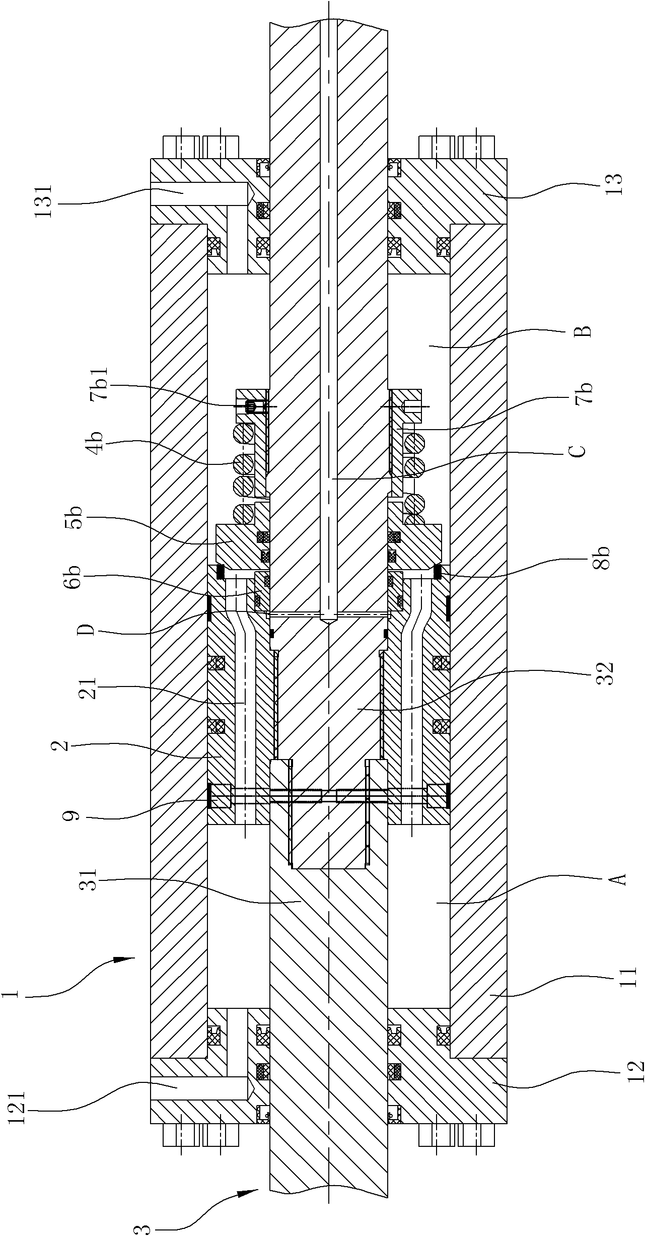
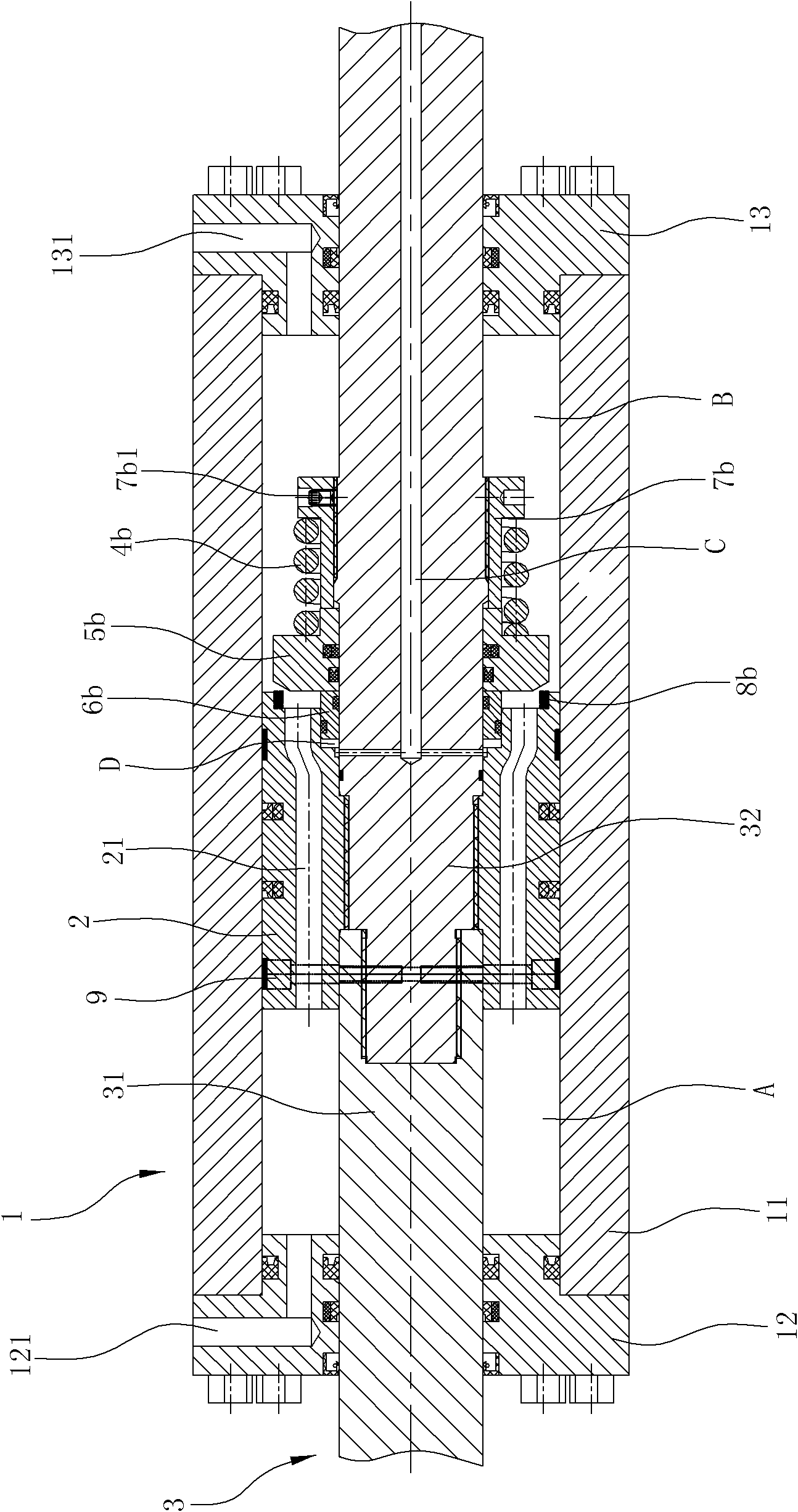
[0027] A hydraulic cylinder, comprising a cylinder body 1, a piston 2 and a piston rod 3, the cylinder body 1 comprising a housing 11 having an axial through hole and a left cover 12 and a right cover 13 closing the openings at both ends of the housing 11, A seal is provided between the left cover 12 and the right cover 13 and the inner wall of the through hole of the housing 11 to form a liquid seal.

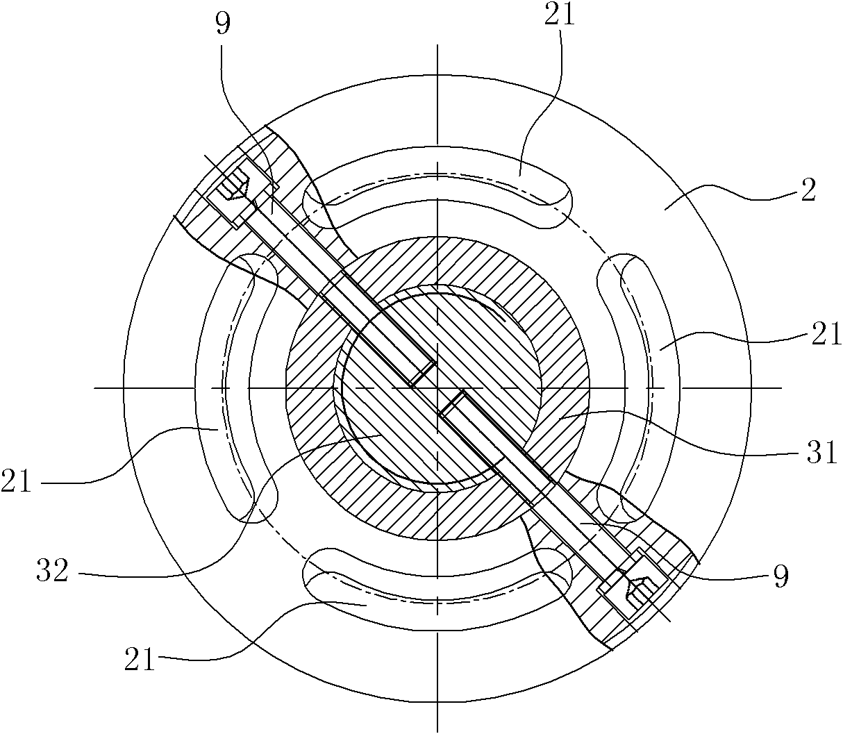
[0028] The piston 2 is set in the cylinder body 1 and can slide axially. There is a seal between the outer circumference of the piston 2 and the inner wall of the cylinder body to form a liquid seal. The piston 2 separates the inner chamber of the cylinder body 1 into a left chamber A which is independent of each other. and the right chamber B, the cylinder b...


PUM


Abstract

The invention relates to a hydraulic cylinder, which comprises a cylinder body, a piston and a piston rod. The piston is arranged in the cylinder body and divides a cavity of the cylinder body into a left cavity and a right cavity, a left oil filling port and a right oil filling port are further arranged on the cylinder body, and the piston is fixedly sleeved on the piston rod. The hydraulic cylinder is characterized in that a flow channel communicated with the left cavity and the right cavity is arranged on the piston, a right spring, a right valve core and a right control sleeve are arranged on the piston rod, and the right spring acts on the right valve core so as to enable the right valve core to keep in the trend that a right outlet of the flow channel is closed. The right control sleeve is arranged on the left side of the right valve core, a high-pressure oil channel communicated with the left end of the right control sleeve is processed on the piston rod, and when high-pressure oil is fed into the high-pressure oil channel, the right control sleeve moves rightwards and drives the right valve core to move rightwards so as to open the right outlet of the flow channel. The hydraulic cylinder is in an inner return type structure, and when the oil cylinder is full of oil, no further oil supplementary is required so that externally-arranged pipelines are simplified. Further, through action of the springs, the valve core can be reset, thereby achieving reliable closing of oil on two sides of the piston and ensuring reliable pressure maintaining of the hydraulic cylinder.

Description

technical field [0001] The invention belongs to the executive element of a fluid control system, in particular to a double-piston-rod hydraulic cylinder. Background technique [0002] The traditional double-piston-rod hydraulic cylinder includes a cylinder body, a piston and a piston rod. The openings at the left and right ends of the cylinder body are closed with cylinder covers. The piston is located in the cylinder body and can slide axially. The cavity is divided into left cavity and right cavity which are independent of each other. There is a sealing structure between the piston, the cylinder head and the inner peripheral wall of the cylinder body to form a liquid seal. The piston rod passes through the piston and is fixed with the piston. The left and right sides of the piston rod The ends pass through the cylinder head located at the left and right ends of the cylinder body respectively and form a liquid seal with the cylinder head. The cylinder body is also provided ...

Claims


Application Information

Patent Timeline
Patent Type & Authority Patents(China)
IPC IPC(8): F15B15/14
Inventor 张策翁振涛洪军王金虎崔剑
Owner 宁波千普机械制造有限公司
Why Eureka
Try Eureka