Optical position sensor

An encoder and optical technology, applied in instruments, measuring devices, converting sensor output, etc., can solve problems such as cost increase, and achieve the effect of rapid signal addition

Inactive Publication Date: 2012-05-02
BAUMER ELECTRIC
View PDF5 Cites 14 Cited by
  • Summary
  • Abstract
  • Description
  • Claims
  • Application Information

AI Technical Summary

Problems solved by technology

This approach also re

Method used


Image

  • Optical position sensor
  • Optical position sensor
  • Optical position sensor

Examples


Example Embodiment

[0039] The present invention can be used not only for rotary encoders and mantelrads, but also for linear position encoders. These embodiments are limited to applications in rotary encoders.

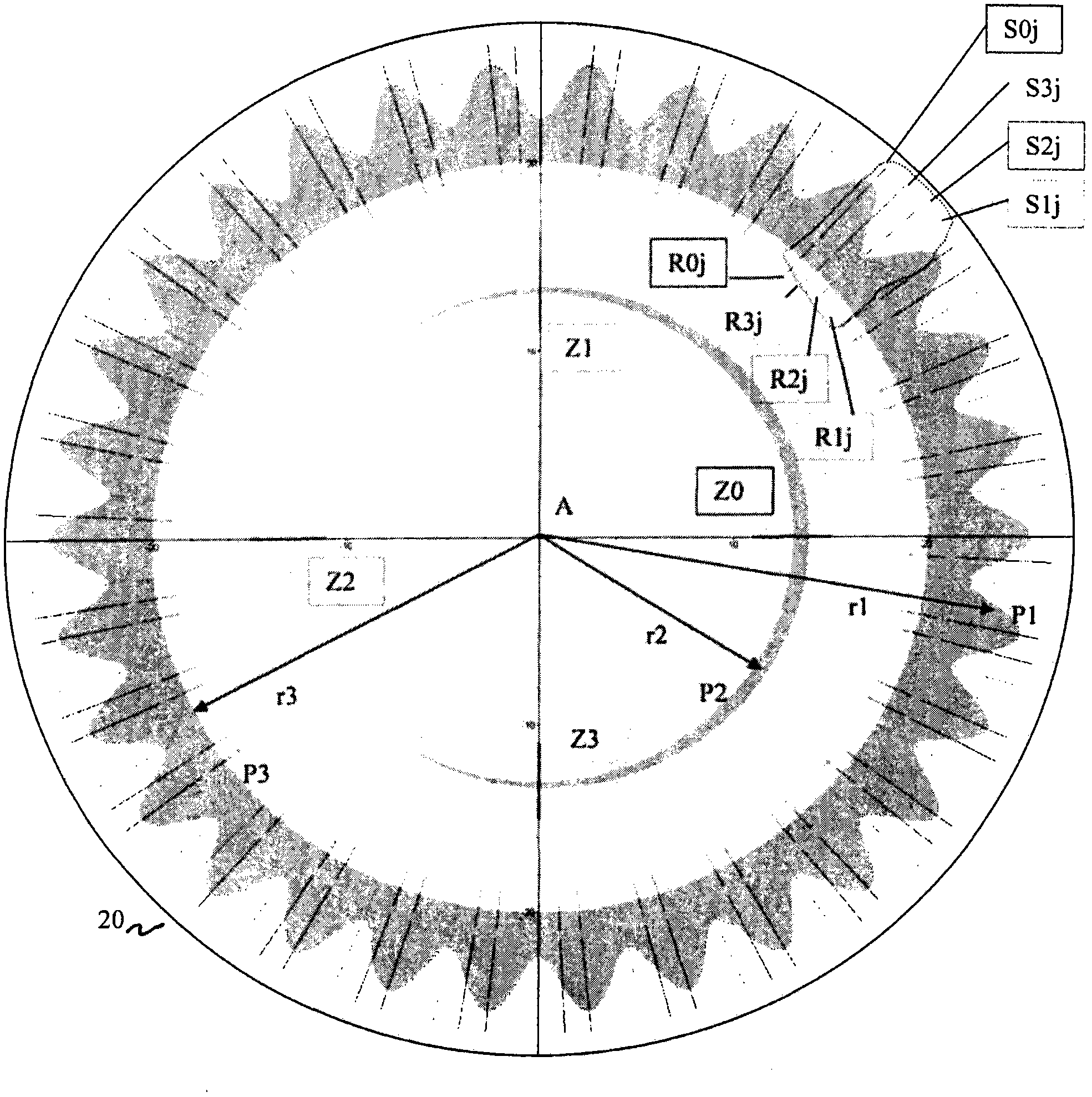
[0040] figure 1 A plan view of the measuring tool 20 and sensor devices Sij, Zi, Rij according to the first embodiment is shown. The measuring tool 1 has a symmetry axis A, and the intersection of the symmetry axis and the measuring tool forms the center of the ring structure described below. The first sinusoidal ring structure P1 has a first period number n1. The second sinusoidal ring structure P2 has a second cycle number n2. In addition, there is a third circular structure P3. The whole sensor device is composed of three partial sensor devices Sij, Rij and Zi. The first partial sensor device Sij is configured to scan the azimuth angle of the first sinusoidal ring structure P1, and the second partial sensor device Zi is configured to An azimuth scan is performed on the second sinusoi...


PUM


Abstract

Provided is an optical position sensor, which relates to a measuring unit having a first ring structure (P1) with a first translucent ring area and a first opaque ring area. A boundary line has a periodic form, particularly a monotonous form and a sine form with an amount of periods between the translucent and the opaque ring areas in azimuth direction. The periodic form includes a first periodic number (n1), at least one light source for lighting the measuring unit, and a first sensor device encircling the center in a ring-shaped arrangement. The first sensor device has at least two sensor groups of the same. The sensor groups are staggered in azimuth direction with an integer period, and the deviation is smaller than 10% of the period, and preferably smaller than 5% of the period, and most preferably smaller than 1% of the period. Each sensor has at least one optical sensor element (Sij) for receiving light of the first ring structure.

Description

technical field [0001] The invention relates to an optical position encoder, in particular an optical rotary encoder, for detecting the position of a shaft rotatable about an axis of rotation. Background technique [0002] Position encoders are commonly used to monitor and control mechanical motion processes. For example, position encoders are used in the construction as rotary encoders for speed detection and control of electric motors. Rotary encoders for determining the angular position by scanning a rotatable shaft in a single or multiple revolutions without contact are known in various embodiments. [0003] EP 1452836 B1 describes a device for measuring the absolute angle of rotation of two members that are rotatable relative to each other using a gauge that is fully illuminated in transmitted light by a light source that is centrally located with respect to the axis of rotation and the gauge Bright. The metrology tool comprises an angular grating structure and is sc...

Claims


Application Information

Patent Timeline
IPC IPC(8): G01D5/347
CPCG01D5/24476G01D5/34707G01D5/2448G01D5/3473
Inventor M・施奈德J・伊勒费尔德B・希勒
Owner BAUMER ELECTRIC
Why Eureka
Try Eureka