
Loading system for test platform of wind generating set

A technology for wind turbines and test platforms, which is used in the testing of mechanical components, the testing of machine/structural components, and the testing of machine gears/transmission mechanisms, which can solve the problem of unrealistically testing the rationality and reliability of the transmission chain of wind turbines. , can not simulate the bending moment of the main shaft system, can not meet the needs of wind turbine testing and other issues

Active Publication Date: 2012-05-02
CRRC WIND POWER(SHANDONG) CO LTD
View PDF3 Cites 19 Cited by
  • Summary
  • Abstract
  • Description
  • Claims
  • Application Information

AI Technical Summary

Problems solved by technology

However, the test bench widely used in the market at present adopts the mode of dragging the motor to drive the gearbox and then directly connecting the input end of the wind turbine. Although the electrical performance and related parameters of the wind turbine can be tested, the test bench can only provide wind power The torque required by the generator set, but cannot simulate the thrust generated by the actual wind conditions on the wind force and the bending moment generated by the weight of the wind wheel on the main shaft system, so it is impossible to truly test the rationality and reliability of the wind turbine drive chain
With the increasing power of the unit, the reliability requirements of the unit are getting higher and higher today. The conventional wind turbine test bench that can only provide torque can no longer meet the testing needs of the wind turbine with the rapid development of technology.

Method used


Image

  • Loading system for test platform of wind generating set
  • Loading system for test platform of wind generating set
  • Loading system for test platform of wind generating set

Examples


Embodiment Construction

[0041] The present invention will be further described below in conjunction with the accompanying drawings and embodiments.

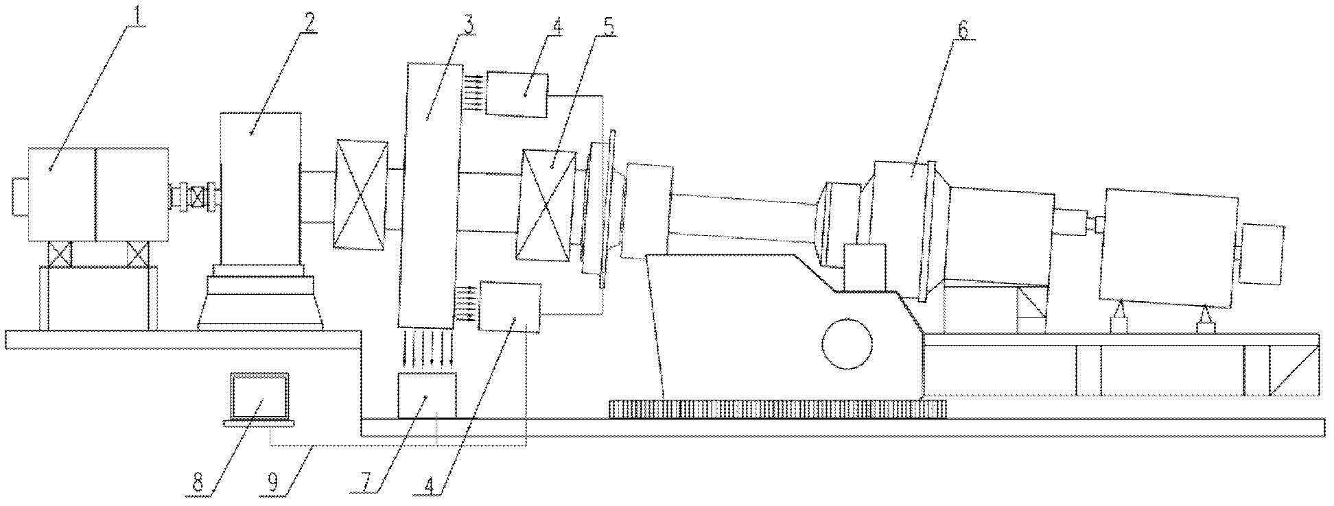
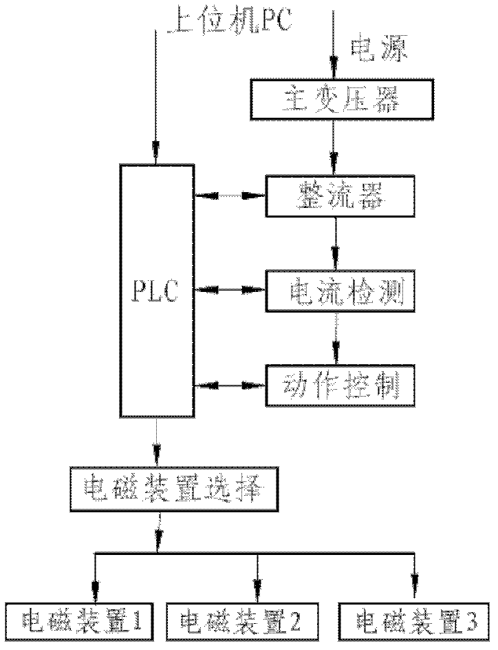
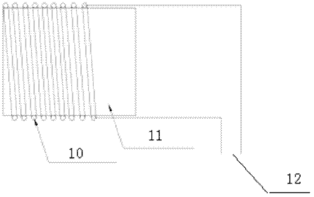
[0042] Such as Figure 1-3 As shown, a loading system for a test platform of a wind power generating set includes a motor 1, the motor 1 is connected to a reduction box 2, and the output shaft of the reduction box 2 is connected to the input shaft of a wind power generating set 6 through a low-speed universal coupling 5 , the shaft portion of the universal coupling 5 is provided with a load simulation part 3, and an electromagnetic generating device is installed on the upper and lower periphery of the load simulation part 3 and at least one side of the left and right sides, and the electromagnetic generating device and the motor 1 are respectively controlled by a control cable. 9 links to each other with control system 8.

[0043] The load simulation part 3 is to add a flange with magnetic properties on the coupling between the output shaft of the gear...


PUM


Abstract

The invention discloses a loading system for a test platform of a wind generating set. The loading system comprises a motor, wherein the motor is connected to a reduction box; an output shaft of the reduction box is connected to an input shaft of the wind generating set through a universal coupler; a load simulating part is arranged on a shaft position of the universal coupler; an electromagnet generating device is additionally arranged on at least one of up and down peripheries and left and right sides of the load simulating part; and the electromagnet generating device and the motor are respectively connected to a control system. According to a congruent relationship between a rotating speed of the generating set and an air speed and a thrust coefficient of the generating set, the control system of the test platform is utilized to solve a thrust value generated by the generating set and calculate a current value for generating the corresponding thrust and gravity by an electromagnetsystem, and the electromagnet system is utilized to load the load simulating part and simulate the thrust, gravity, bending moment parameter, and the like, of a fan under a practical wind condition.

Description

technical field [0001] The invention relates to a wind power generator test technology, in particular to a loading system for a wind power generator test platform. Background technique [0002] At present, the world's environmental situation is deteriorating day by day, among which the use of coal, natural gas, oil and other fuels to generate electricity is an important factor that produces the greenhouse effect. In order to alleviate the fossil energy crisis and protect the global environment, wind energy, as a new type of energy, has been vigorously developed by countries all over the world. However, due to the alternating and unstable characteristics of the wind itself, higher requirements are put forward for the reliability and stability of the wind power generating set. In order to be able to test and test the main parameters and performance of wind turbines, the wind turbine test bench is widely used by major manufacturers as the test equipment for wind turbines. [...

Claims


Application Information

Patent Timeline
IPC IPC(8): G01M13/00G01M13/02
Inventor 于良峰吴得宗何金海吴树梁李刚强赵磊
Owner CRRC WIND POWER(SHANDONG) CO LTD
Learn More