Orthoptic synthetic aperture laser imaging radar

A technology of synthetic aperture laser and imaging radar, which is applied in the direction of instruments, measuring devices, and utilization of re-radiation, etc., can solve problems such as complex delay line technology, and achieve the effect of simple electronic equipment

Active Publication Date: 2012-05-02
SHANGHAI INST OF OPTICS & FINE MECHANICS CHINESE ACAD OF SCI
View PDF2 Cites 35 Cited by
  • Summary
  • Abstract
  • Description
  • Claims
  • Application Information

AI Technical Summary

Problems solved by technology

In order to reduce the beat frequency and suppress the influence of nonlinear chirp in side-looking synthetic aperture radar, the delay of the local oscillator beam needs to be close to the two-way distance of the target, so a long-distance optical delay line with minimal phase change is required. This delay line technique is quite complex (Refs 2, 4)

Method used


Image

  • Orthoptic synthetic aperture laser imaging radar
  • Orthoptic synthetic aperture laser imaging radar
  • Orthoptic synthetic aperture laser imaging radar

Examples


Embodiment Construction

[0039] The present invention will be described in further detail below in conjunction with the accompanying drawings and embodiments, but the protection scope of the present invention should not be limited thereby.

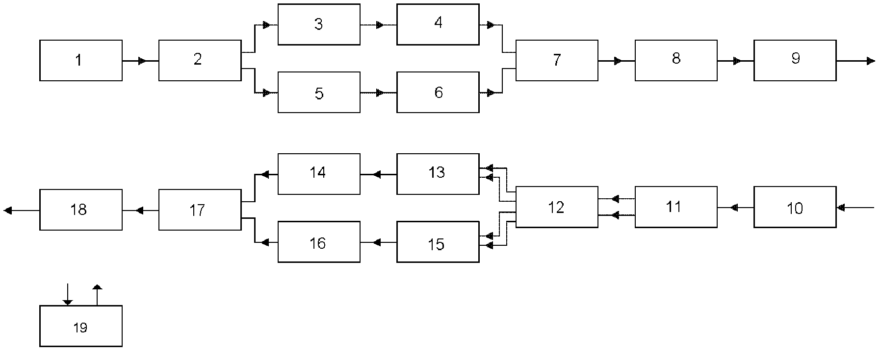
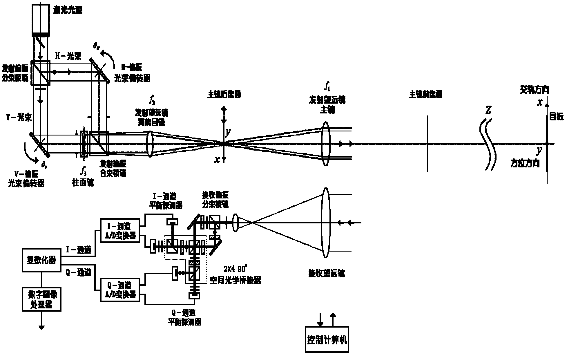
[0040] see first figure 1 , figure 1 It is a principle diagram of the direct-looking synthetic aperture laser imaging radar of the present invention. As can be seen from the figure, the direct-looking synthetic aperture laser imaging radar of the present invention is composed of a transmitting end, a receiving end and a control computer 19, and the transmitting end includes a laser light source 1, a transmitting polarization beam splitter 2, and an H-(horizontal) polarization optical path Beam deflector 3, H-polarization optical path conversion mirror 4, V-(vertical) polarization optical path beam deflector 5, V-polarization optical path conversion mirror 6, emission polarization beam combiner 7, emission telescope eyepiece 8; emission telescope main mirror 9 Th...


PUM


Abstract

The invention relates to an orthoptic synthetic aperture laser imaging radar. The orthoptic synthetic aperture laser imaging radar comprises a laser light source, a transmission polarization beam splitter, a horizontal polarization optical path beam deflector, a horizontal polarization optical path transform lens, a vertical polarization optical path beam deflector, a vertical polarization optical path transform lens, a transmission polarization beam combiner, a transmitter telescope ocular, a transmitter telescope primary lens, a receiver telescope, a receiving polarization beam splitter, a 2 * 490 DEG optical bridge, an inphase channel balanced detector, an inphase channel A / D (analogue / digital) converter, a 90 DEG of phase shift channel balanced detector, a 90 DEG of phase shift channel A / D (analogue / digital) converter, a pluralizing processor, a digital image processor and a control computer. The orthoptic synthetic aperture laser imaging radar automatically eliminates phase changes and interference of atmosphere, motion platforms, optical radar systems and speckles, has high resolution imaging in larger optical footprint and larger receiving aperture, does not need optical delay lines, does not need real-time beat frequency signal phase synchronization, does not have shadows during imaging, and can be used for various lasers with single-module and single-frequency properties.

Description

technical field [0001] The invention relates to laser radar, which is a direct-looking synthetic aperture laser imaging radar. The principle adopts coaxial scanning astigmatic wavefront emission and self-difference detection complex number reception, and performs spatial linear phase term modulation resolution imaging in the cross-track direction. The quadratic term phase history matching filter imaging is carried out in the orbit direction, so it can automatically eliminate the phase change and interference caused by the atmosphere, moving platform, lidar system and speckle, and can be used under a larger optical toe and a larger receiving aperture Produces high-resolution imaging, allows the use of low-quality receiving optics, does not require optical delay lines, does not require real-time beating signal phase synchronization, imaging without shadows, can use a variety of lasers with single-mode and single-frequency properties, and simultaneously Because the complex number...

Claims


Application Information

Patent Timeline
Patent Type & Authority Applications(China)
IPC IPC(8): G01S17/89G01S7/481
Inventor 刘立人
Owner SHANGHAI INST OF OPTICS & FINE MECHANICS CHINESE ACAD OF SCI
Why Eureka
Try Eureka