
Solar photovoltaic plate solar orientation adjusting device and adjusting method employing same

A technology of solar photovoltaic panels and adjustment devices, which is applied in the field of solar photovoltaics and can solve the problems of solar photovoltaic panels with reduced solar energy receiving capacity and low power generation

Inactive Publication Date: 2012-05-02
湖南海松能源科技有限公司
View PDF6 Cites 3 Cited by
  • Summary
  • Abstract
  • Description
  • Claims
  • Application Information

AI Technical Summary

Problems solved by technology

[0003] In view of the defects in the prior art that it is difficult for ordinary users to accurately adjust the sun-facing angle of the solar photovoltaic panel, resulting in a decrease in the solar energy receiving capacity of the solar photovoltaic panel and low power generation, the present invention provides a solar photovoltaic panel sun-facing adjustment device, which has a simple structure. Easy to operate, ordinary users can use this device to precisely adjust the sun-facing angle of solar photovoltaic panels to maximize the use of solar energy

Method used


Image

  • Solar photovoltaic plate solar orientation adjusting device and adjusting method employing same
  • Solar photovoltaic plate solar orientation adjusting device and adjusting method employing same
  • Solar photovoltaic plate solar orientation adjusting device and adjusting method employing same

Examples


Embodiment 1

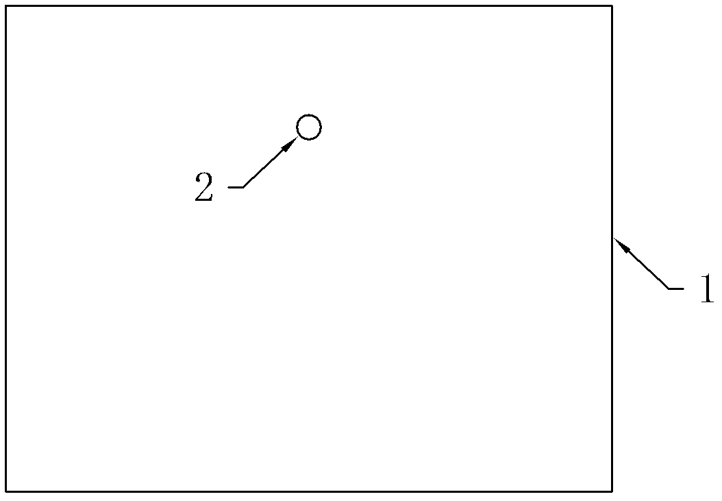
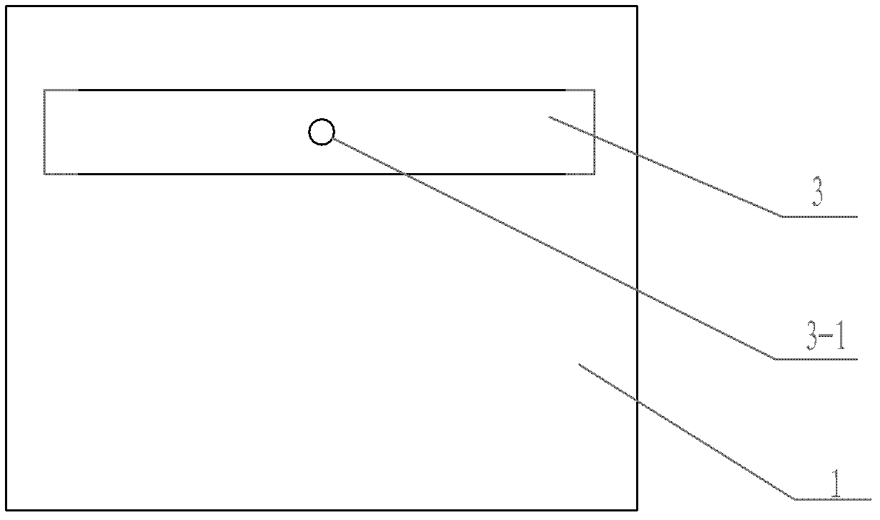
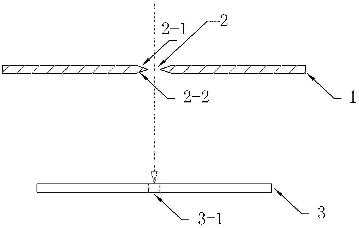
[0030] Such as Figure 1-3 Shown is a schematic diagram of a solar photovoltaic panel installed with a sunning adjustment device. figure 1 Among them, a through hole is provided at any position on the surface of the solar photovoltaic panel 1 as the light-transmitting hole 2 , and sunlight can directly pass through the light-transmitting hole 2 to the scale plate 3 behind the solar photovoltaic panel 1 . image 3 As shown, a scale plate 3 is arranged at the lower rear of the back side of the solar photovoltaic panel 1, the plate surface of the scale plate 3 is parallel to the plate surface of the solar photovoltaic panel 1, and the origin O3-1 is marked on the plate surface (see figure 2 ), the straight line determined by the light-transmitting hole 2 (preferably its center point, which improves the accuracy) and the origin O3-1 (preferably the center point of the origin O, to improve the accuracy) is perpendicular to the solar photovoltaic panel 1 and the scale plate 3, so ...

Embodiment 2

[0039] The difference between this embodiment and Embodiment 1 is that: the scale plate 3 in this embodiment is marked with a horizontal X-axis with a time scale and a vertical Y-axis with an elevation scale. See Figure 4 , the back side of the scale plate 3 is marked with the horizontal axis X axis parallel to the horizontal plane and the vertical axis Y axis perpendicular to the horizontal axis, the time scale x is marked on the X axis, and the range of x in the present embodiment is from 9 in the morning to night At 17:00, of course, other ranges can also be selected, and a period of time is selected from them according to the daytime time of the place where the solar photovoltaic panel 1 is used, which is the range of the X-axis. The marking method of the specific time scale x on the X-axis is as follows: at noon, adjust the angle of the solar photovoltaic panel 1 according to the method that the light spot falls into the origin position (of course, other methods can also...


PUM


Abstract

To a defect that in the prior art, a common user is hard to accurately adjust a solar orientation angle of a solar photovoltaic plate, thus solar energy reception capability of the solar photovoltaic plate is decreased and generating capacity is low, the invention provides a solar photovoltaic plate solar orientation adjusting device which comprises a scale plate and a light transmission hole opened in a face of the solar photovoltaic plate. The light transmission hole is a through hole. The scale plate is under a back side of the solar photovoltaic plate and a face of the scale plate is parallel to the face of the solar photovoltaic plate. The face of the scale plate is provided with an original point identity. A straight line determined by the light transmission hole and the original point is perpendicular to the face of the solar photovoltaic plate. The device has a simple structure and easy operation, and the common user completely can employ the device to realize accurate adjustment of the solar orientation angle of the solar photovoltaic plate to achieve maximization utilization of solar energy.

Description

technical field [0001] The invention belongs to the technical field of solar photovoltaics, and in particular relates to a sun-facing adjustment device for a solar photovoltaic panel and a sun-facing adjustment method using the device. Background technique [0002] In order to improve the power generation of solar cells, in the prior art, angle-adjustable solar photovoltaic panels are usually used to adjust the angle of the light-receiving surface of the solar photovoltaic panel by adjusting the angle of the solar photovoltaic panel, but it is difficult for ordinary users to directly adjust the solar photovoltaic panel with professional knowledge. The sunlight angle of photovoltaic panels, especially the angle between sunlight and light in different latitudes in different seasons, is different, resulting in a decline in the solar energy receiving capacity of solar photovoltaic panels, and the inability to maximize the use of solar light. Contents of the invention [0003] ...

Claims


Application Information

Patent Timeline
Patent Type & Authority Applications(China)
IPC IPC(8): G05D3/00
Inventor 牟勇刚戴良辉
Owner 湖南海松能源科技有限公司
Learn More