
Pedal device for electronic percussion instrument

A technology for percussion instruments and pedals, which is applied to percussion instruments, electroacoustic instruments, musical instruments, etc., can solve the problems of vibration and impact noise, and achieve the effect of improving the feeling of depression and increasing the inertial force.

Inactive Publication Date: 2012-05-02
YAMAHA CORP
View PDF6 Cites 4 Cited by
  • Summary
  • Abstract
  • Description
  • Claims
  • Application Information

AI Technical Summary

Problems solved by technology

In particular, this vibrating and percussive sound feels disturbing in electronic drums compared to acoustic drums

Method used


Image

  • Pedal device for electronic percussion instrument
  • Pedal device for electronic percussion instrument
  • Pedal device for electronic percussion instrument

Examples


Embodiment Construction

[0032] Embodiments of the present invention will be described with reference to the drawings.

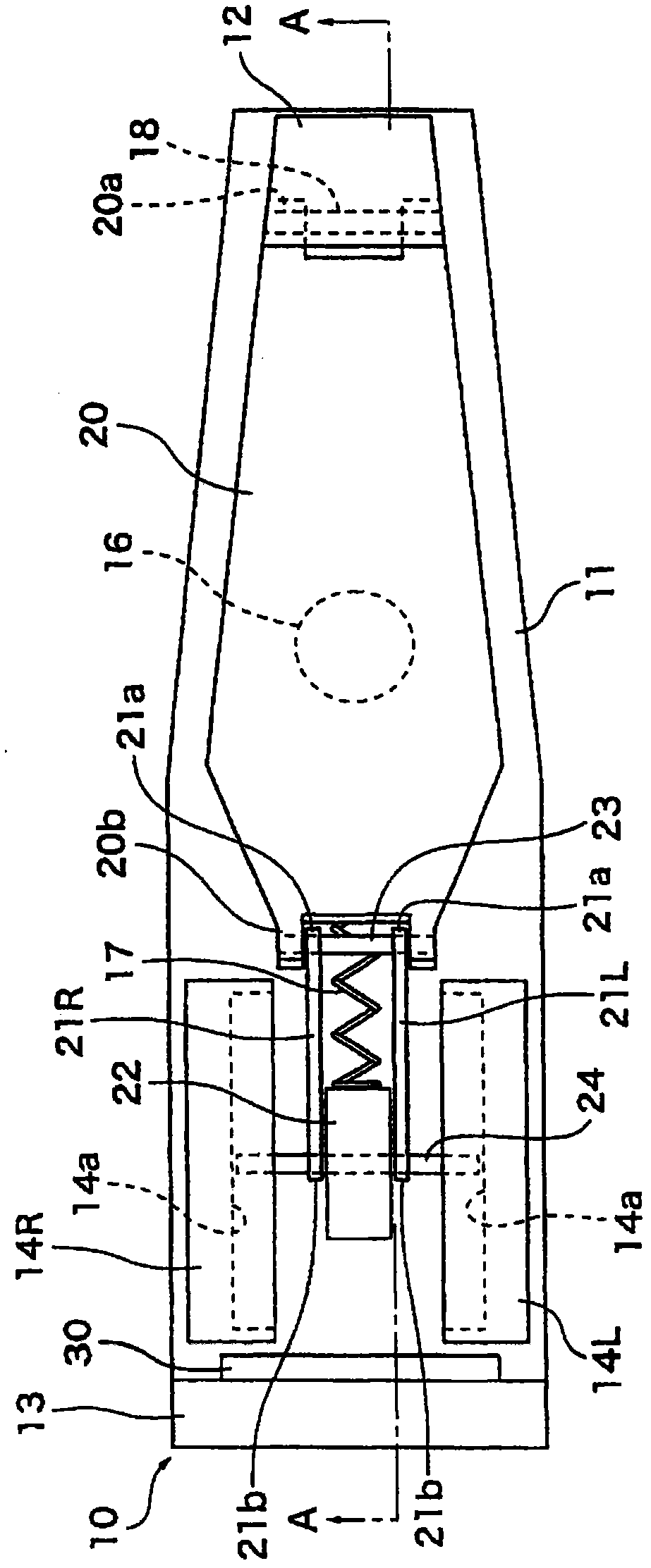
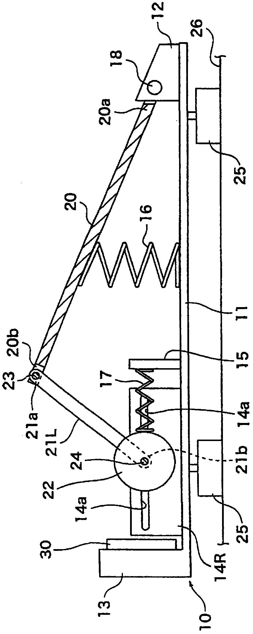
[0033] Figure 1A with Figure 1BThey are respectively a top view and a bottom view of a pedal device for an electronic percussion instrument according to an embodiment of the present invention. Figure 2A with Figure 2B for along Figure 1A A cross-sectional view taken along line A-A in .

[0034] The pedal device is configured as a kick pedal for an electronic bass drum as an electronic percussion instrument. The pedal device is provided on the floor 26 and is performed by pressing down or stepping on the pedal 20 . Figure 2A The state (that is, the non-operating state or the initial state) in which the pedal 20 is in the initial position of pressing down is shown, and Figure 2B A state in which the pedal 20 is at the position where the depression is completed (that is, a state where the depression is completed) is shown.

[0035] Hereinafter, the front-rear direction and ...


PUM


Abstract

A pedal device for an electronic percussion instrument, including: a base; a foot board supported at its first end portion to the base and configured to pivot by depression; an arm rotatably supported at its first end at a pivot point located near to a second end portion of the foot board, the arm being pivotable about the pivot point; a mass portion provided near to a second end of the arm; a regulating portion for regulating a locus of displacement of the mass portion when the foot board is moved from a depression start position to a depression end position; and a stopper portion provided on the base for defining the depression end position by contacting the mass portion in a forward stroke of depression, the regulating portion regulating the locus of the displacement of the mass portion so as not to contain a downward component in the forward stroke.

Description

technical field [0001] The invention relates to a pedal device for an electronic percussion instrument. Background technique [0002] There is conventionally known a pedal device for electronic percussion instruments. In the pedal device described in the patent document JP-A-2008-145464, a footboard is pivotally supported on a base, and a weight is provided at a free end of the footboard. In addition, a tension coil spring is provided at the free end of the footboard. This known pedal device is intended to achieve a depression feel close to that of an acoustic drum by virtue of the inertial force of a weight and the load increase of a tension coil spring when the pedal is depressed or stepped on. [0003] However, in the pedal device disclosed in the patent document JP-A-2008-145464, a weight is provided on the footboard. Accordingly, the weight needs to be arranged so as not to interfere with the operation of the pedals, so there are various constraints on the size and c...

Claims


Application Information

Patent Timeline
Patent Type & Authority Applications(China)
IPC IPC(8): G10H1/34G10H3/14G10D13/00
CPCG10D13/00G10H3/14G10H1/34G10H1/348G10H2230/275G10H3/146G10H2230/281G10H1/00G10H2230/291G10H2230/361G10H1/32Y10T74/20189Y10T74/20195
Inventor 桥本隆二
Owner YAMAHA CORP
Learn More