Novel rotating travelling-wave ultrasonic motor

An ultrasonic motor, rotary type technology, applied in the direction of generator/motor, piezoelectric effect/electrostrictive or magnetostrictive motor, electrical components, etc., can solve the instability of ultrasonic motor, heavy local friction, affecting ultrasonic motor Work performance and service life and other issues, to achieve the effect of improving the maximum output torque and efficiency, and prolonging the service life

Inactive Publication Date: 2012-05-02
JIMEI UNIV
View PDF3 Cites 35 Cited by
  • Summary
  • Abstract
  • Description
  • Claims
  • Application Information

AI Technical Summary

Problems solved by technology

However, due to the limitations of its structure, the load exerted by the pressurized spring on the rotor is not balanced in the radial direction, resulting in uneven contact between the stator and the rotor in the radial direction, resulting in heavy local friction during operation. At the same time, the stator and rotor have The radial sliding friction loss causes the instability of the ultrasonic motor, which seriously affects the working performance and service life of the ultrasonic motor. So far, no one in the world has proposed a better solution to this problem of the ultrasonic motor.

Method used


Image

  • Novel rotating travelling-wave ultrasonic motor
  • Novel rotating travelling-wave ultrasonic motor
  • Novel rotating travelling-wave ultrasonic motor

Examples


Embodiment Construction

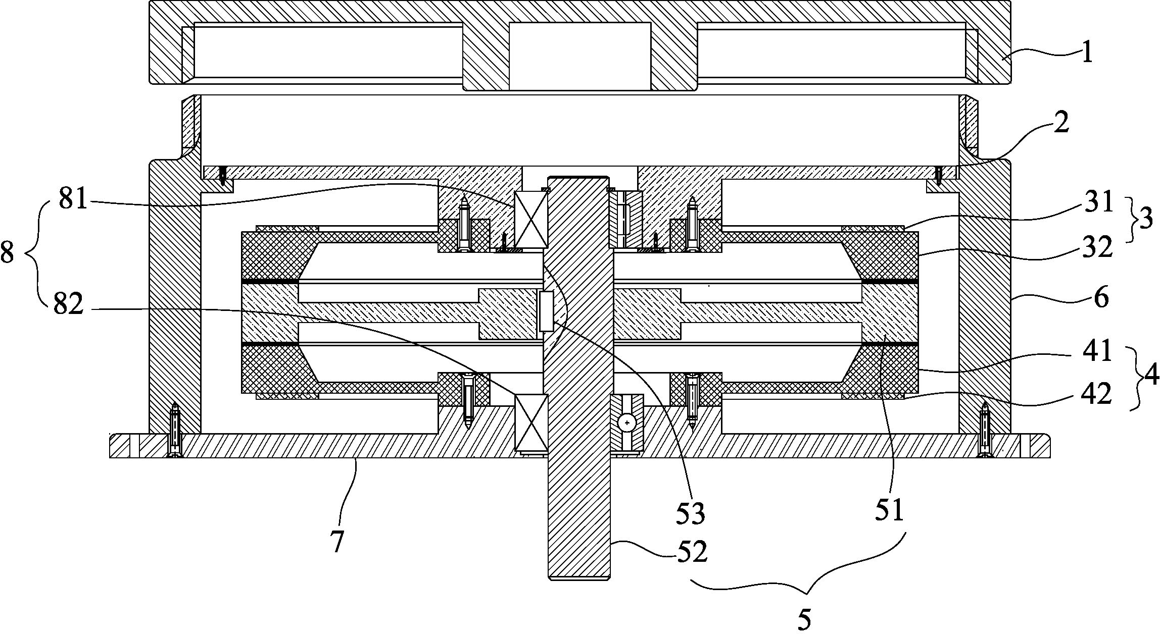
[0016] Such as figure 1 As shown, the present invention is a new rotary traveling wave ultrasonic motor, which includes an outer cover 1, a web 2, an upper stator assembly 3, a lower stator assembly 4, a rotor 5, a cylindrical shell 6, a base 7, and a bearing 8.

[0017] Described rotor 5 is made up of rotating shaft 51, rotating disc 52 and flat key 53. The center of the turntable 52 is fixedly sleeved on the rotating shaft 51 through a flat key 53 .

[0018] The outer cover 1 is threadedly connected to the top of the cylindrical casing 6, and the middle part thereof protrudes downwards. The raised platform is used to depress the web-type deformation so as to obtain a pre-pressure between the stator and the rotor. The cylindrical casing 6 The bottom is fixed on the base 7, the web 2 is sleeved on the upper part of the inner cavity of the cylindrical shell 6, and an accommodating space is formed between the web 2 and the base 7; the stator (piezoelectric vibrator) is sleeved ...


PUM


Abstract

The invention discloses a novel rotating travelling-wave ultrasonic motor. The ultrasonic motor comprises the following main parts: two stators, a rotor, a pedestal, a friction pad, a check ring, a bearing and the like. The two stators which are in a same shape are symmetrically arranged and compact on two end faces of the rotor. Working faces of the two stators can be parallelly contacted with a surface of the rotor so that a contact surface of the stators and the rotor bears stress evenly. In a current rotating travelling-wave ultrasonic motor based on a single stator structure, radial contact between the stator and the rotor is nonuniform, a contact scope is small, and radial sliding friction losses and other defect are existed in the stator and the rotor. By using the ultrasonic motor of the invention, the above defects can be overcome. A maximum output torque and an efficiency of the rotating travelling-wave ultrasonic motor can be increased and a service life of the rotating travelling-wave ultrasonic motor can be prolonged.

Description

technical field [0001] The invention belongs to the technical field of electric drive and control motors, and relates to the research of a novel ultrasonic motor, in particular to a novel rotary traveling wave ultrasonic motor. Background technique [0002] With the rapid development of science and technology, electronic equipment, precision instruments, optical systems and aerospace equipment are increasingly miniaturized and refined, which puts forward higher and higher requirements for motor performance indicators, such as low-speed high-torque, fast and precise positioning, low Noise, no electromagnetic interference, etc. Due to the limitation of working principle and structural form, the traditional electromagnetic motor has been unable to meet these requirements. Over the years, many scholars and experts around the world have been working on the development of various new micro-special motors to meet the requirements of miniaturization and precision of various devices...

Claims


Application Information

Patent Timeline
Patent Type & Authority Applications(China)
IPC IPC(8): H02N2/16
Inventor 纪跃波侯飞
Owner JIMEI UNIV
Why Eureka
Try Eureka