Reference signal mapping method and device

A technology of reference signal and mapping method, applied in the directions of pilot signal allocation, transmission path sub-channel allocation, and error prevention/detection through diversity reception, which can solve problems such as poor cooperative transmission performance, and improve compatibility and effect. , Improve the effect of joint transmission performance

Active Publication Date: 2012-05-02
ZTE CORP
View PDF3 Cites 41 Cited by
  • Summary
  • Abstract
  • Description
  • Claims
  • Application Information

AI Technical Summary

Problems solved by technology

[0015] The main purpose of the present invention is to provide a reference signal mapping method and device to solve the

Method used


Image

  • Reference signal mapping method and device
  • Reference signal mapping method and device
  • Reference signal mapping method and device

Examples


Embodiment 1

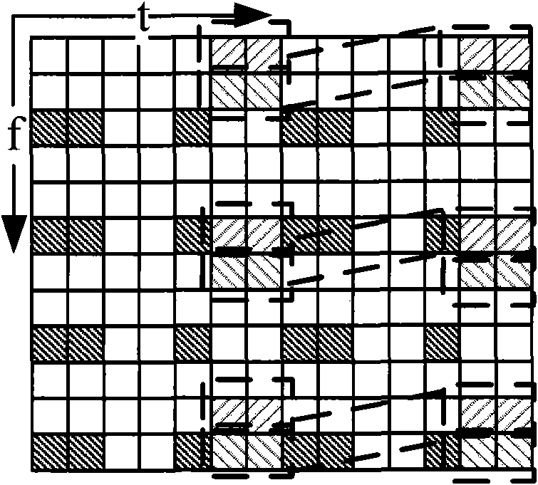
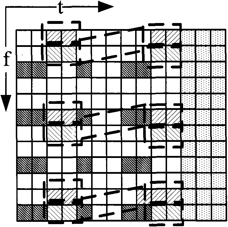
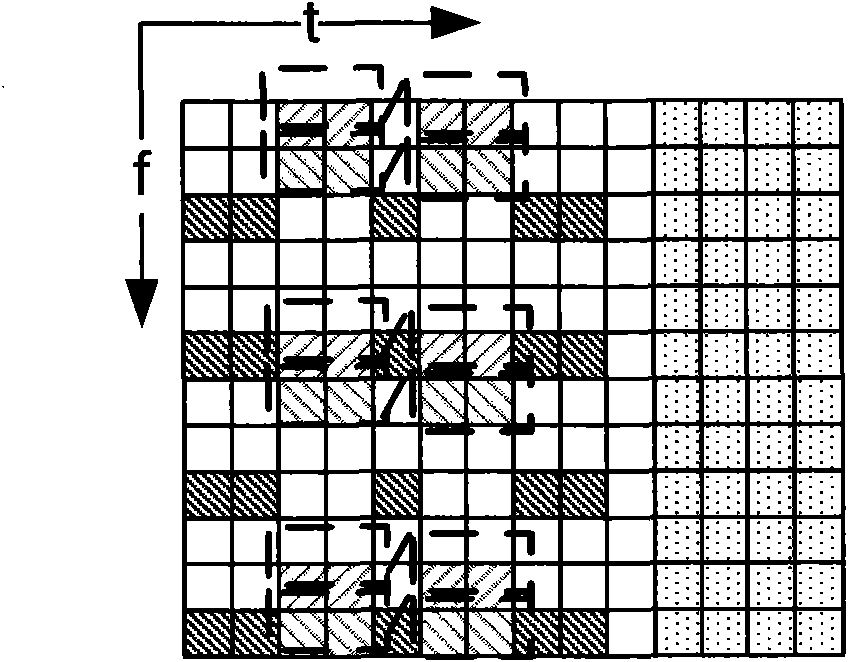
[0054] This embodiment combines the above-mentioned embodiments and preferred implementation modes therein. This embodiment provides a reference signal mapping method. In this embodiment, a specific mapping method for demodulation reference signals during normal CP is implemented. The method Including the following steps:

[0055] Step 1: Use the generation method of the DMRS sequence in LTE to generate the DMRS sequence according to formula (1), the length of the DMRS sequence is generated according to the maximum system bandwidth, and the maximum bandwidth of the system is passed through the number of RBs characterization.

[0056] r ( m ) = 1 2 ( 1 - 2 · c ( 2 m ) ) + ...

Embodiment 2

[0062] This embodiment combines the above-mentioned embodiments and preferred implementation modes therein. This embodiment provides a method for mapping reference signals. In this embodiment, a specific mapping method for demodulating reference signals when extending CP is implemented. The method Including the following steps:

[0063] Step 1: When extending the cyclic prefix, the generation method of the DMRS sequence generates the DMRS sequence according to the formula (3), and the length of the sequence is generated according to the maximum system bandwidth, and the maximum bandwidth of the system is determined by the number of RBs characterization.

[0064] For normal subframes:

[0065] r ( m ) = 1 2 ( 1 - 2 · c ( 2 m ...

Embodiment 3

[0073] This embodiment combines the above-mentioned embodiments and preferred implementation modes therein. This embodiment provides a method for mapping reference signals. In this embodiment, a specific mapping method for CSI-RS is implemented. The method includes the following steps:

[0074] Step 1: The measurement reference signal sequence is generated according to formula (6), and the length of the sequence is also determined according to the maximum system bandwidth.

[0075] r l , n s ( m ) = 1 2 ( 1 - 2 · c ( 2 m ) ) + j 1 2 ...


PUM


Abstract

The invention discloses a reference signal mapping method and a device. The method comprises the following steps that: a maximal systematic bandwidth is used for generating a reference signal sequence; a reference sequence to be mapped is selected from the generated reference signal sequence to be mapped, and the mapped reference sequence is a reference signal sequence corresponding to the maximal systematic bandwidth on the identical resource position. Through the method and the device, the compatibility of the reference signal mapping and coordination transmission is improved, and the coordination combined transmission performance can be further improved.

Description

technical field [0001] The present invention relates to the communication field, in particular, to a reference signal mapping method and device. Background technique [0002] The high-order multi-antenna technology is one of the key technologies of the Long Term Evolution Advanced (LTE-A for short) system, and is used to increase the transmission rate of the system. The Long Term Evolution can also be expressed as LTE-Advanced. In order to achieve channel quality measurement and data demodulation after the introduction of high-order multi-antenna technology, the LTE-A system defines two types of reference signals: demodulation reference signal (Demodulation Reference Signal, referred to as DMRS) and channel quality measurement reference signal ( Channel State Information-Reference Signal, referred to as CSI-RS), wherein the DMRS is used for demodulation of a physical downlink shared channel (Physical Downlink Shared Channel, referred to as PDSCH). The CSI-RS used for channe...

Claims


Application Information

Patent Timeline
IPC IPC(8): H04L27/26H04L1/06
CPCH04L5/0048
Inventor 孙云锋戴博郭森宝张文峰张峻峰
Owner ZTE CORP
Why Eureka
Try Eureka