Light source device, illuminating device, backlight device, liquid crystal display device, and display device
A technology for a light source device and a display device, which is applied to the direction of the lighting device, the parts of the lighting device, the light source, etc., can solve the problem of confirming the orientation of the circuit board, and achieve the effect of easy identification
- Summary
- Abstract
- Description
- Claims
- Application Information
AI Technical Summary
Problems solved by technology
Method used
Image
Examples
Embodiment approach 1-1
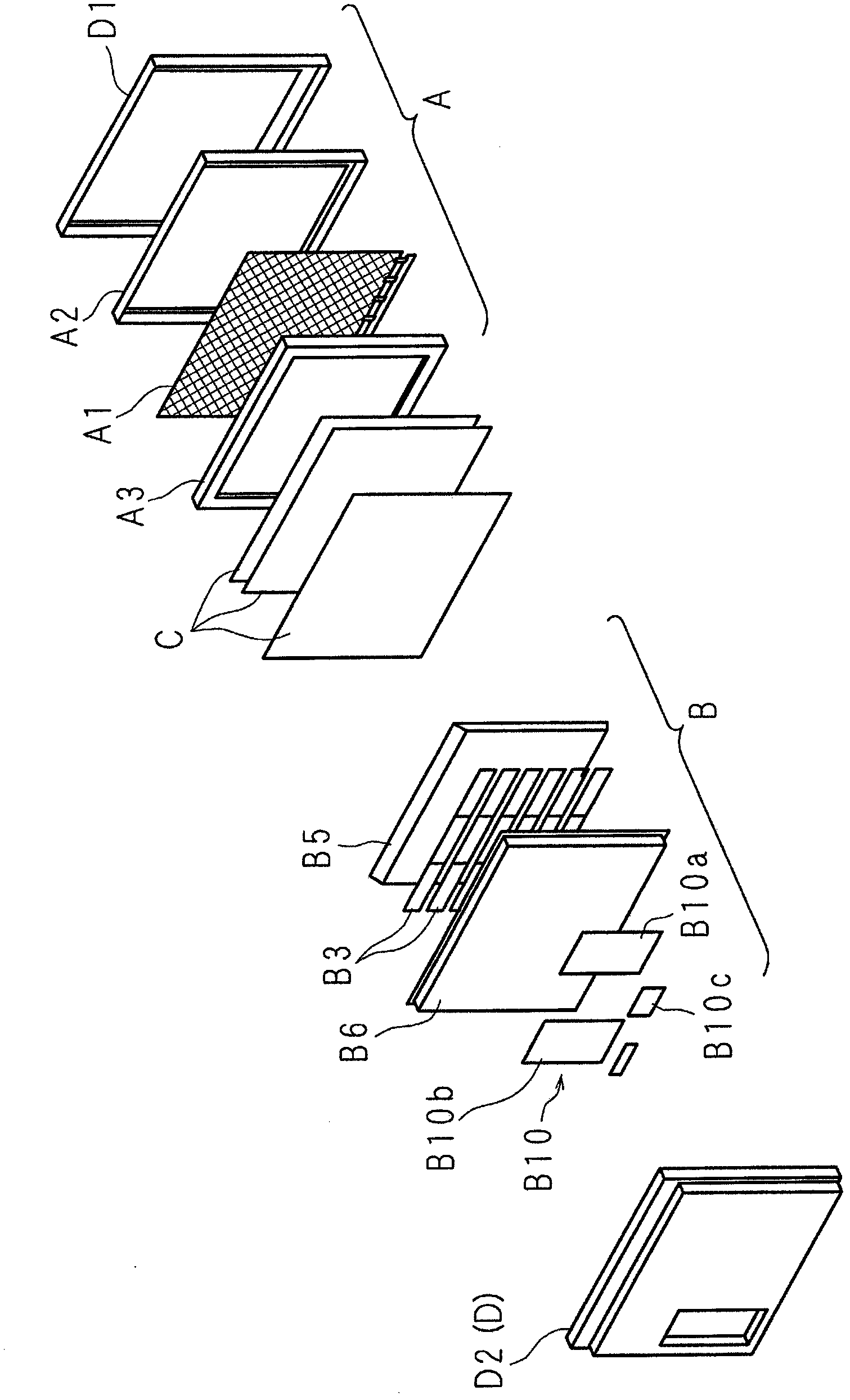
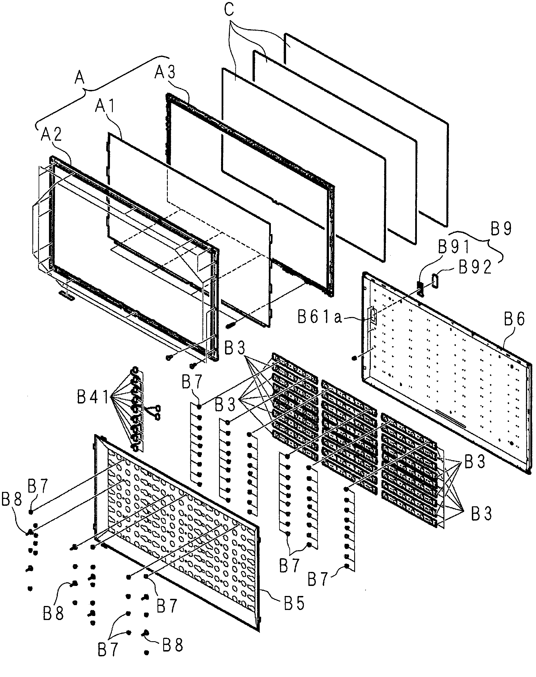
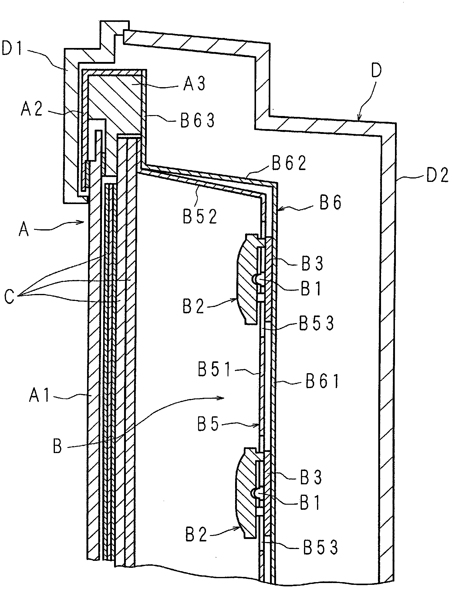
[0362] Figure 29 It is a perspective view showing the structure of the light source device according to the present invention, Figure 30 is a plan view showing the structure of the light source device, Figure 31 It is a plan view showing the structure obtained by omitting the reflection sheet of the light source device, Figure 32 It is an enlarged cross-sectional view showing a part of the structure of the light source device.
[0363] The illustrated light source device (B) is installed on the rear side of the display unit in the thin display device provided with the display unit (A). (B) includes: a plurality of light emitting diodes 1 (B1), which are arranged side by side in a grid shape as light sources; a plurality of light emitting diode substrates 2 (B3), and the plurality of light emitting diode substrates 2 (B3) arranged side by side in multiple rows, the light emitting diode 1 is installed on one surface 2a; a plurality of connectors 3 (B4), the plurality of c...
Embodiment approach 1-2
[0384] Figure 38 It is a developed front view showing another configuration of the main part of the reflection sheet included in the light source device according to the present invention. This light source device adopts the following structure: that is, a substantially V-shaped cutout portion 57 is provided at the corner 52a of the frame portion 52 instead of providing three second strips at the corner of the frame portion 52 of the reflection sheet 5 (B5). The folding line 53 bends the four frame parts 52 connected to the four sides of the flat part 51 obliquely with respect to the flat part 51 at the first folding line 5b, and the two edge parts 57a, 57a of the cutout part 57 Together, and utilize double-sided adhesive tape 55 to keep this combined state.
[0385] The reflection sheet 5 formed of a rectangular synthetic resin sheet material has a flat portion 51 smaller than the plate portion 61 of the supporting case 6, and four sides of the flat portion 51 connected at ...
Embodiment approach 1-3
[0388] Figure 39 It is a developed front view showing another structure of the main part of the reflection sheet included in the light source device according to the present invention, Figure 40 It is an enlarged front view showing other structures of the main part of the reflective sheet. This light source device adopts the following structure: that is, three second folding lines 53 extending from the corners 51a of the flat portion 51 of the reflective sheet 5 to the periphery of the frame body portion 52 and one cutout 58 are provided instead of the corners 51a of the flat portion 51 of the reflective sheet 5. The corner 52a of the frame part 52 is provided with a cutout 57, the corner 52a of the frame part 52 is formed by the second folding line 53, and the end parts of the adjacent frame parts 52 are combined with each other by a cutout 58. The double-sided tape maintains the closed state and the corners 52a.
[0389] The cutouts 58 are arranged to extend from the cor...
PUM
 Abstract
Description
Claims
Application Information
 - R&D
- Intellectual Property
- Life Sciences
- Materials
- Tech Scout
- Unparalleled Data Quality
- Higher Quality Content
- 60% Fewer Hallucinations
Browse by: Latest US Patents, China's latest patents, Technical Efficacy Thesaurus, Application Domain, Technology Topic, Popular Technical Reports.
© 2025 PatSnap. All rights reserved.Legal|Privacy policy|Modern Slavery Act Transparency Statement|Sitemap|About US| Contact US: help@patsnap.com


