
Centrifugal type microfluidic device

A microfluidic device, centrifugal technology, applied in instrumentation, chemical/physics/physicochemical processes, analytical materials, etc., can solve the problems of overlapping rotation speed ranges, unspecified valve positions, and inability to fully exert fluid effects. , achieve the effect of avoiding the sequential release sequence, improving the breakthrough of the speed gap and the stability of the device

Inactive Publication Date: 2012-05-09
AMPOC FAR EAST CO LTD
View PDF10 Cites 20 Cited by
  • Summary
  • Abstract
  • Description
  • Claims
  • Application Information

AI Technical Summary

Problems solved by technology

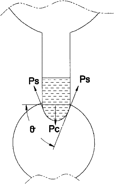
[0006] However, the above-mentioned patents and documents only proposed to use the shape of the valve and the hydrophilic and hydrophobic properties of the surface to increase the centrifugal force to break through the control of the valve, and the prediction of the breakthrough speed of the valve, but they did not clearly propose the position of the valve, especially the position close to the center of the circle, and its control of fluid flow. The relevance of the effect of
Secondly, most of the microfluidic systems in the prior art set the microchannel structure on the disk at a position with a larger radius from the center of the circle, because more microchannels can be set there, but this channel design will The breakthrough speed of the valve will be lower than about 2000RPM; because the breakthrough speed of each valve is a distribution range rather than a certain value, if there is only 2000RPM speed operation space, it will cause the breakthrough speed of the valves with similar radius positions to be lower than 2000RPM. The ranges overlap with each other, and the effect of sequential release of fluids cannot be fully exerted

Method used


Image

  • Centrifugal type microfluidic device
  • Centrifugal type microfluidic device
  • Centrifugal type microfluidic device

Examples


Embodiment

[0059] 1. Determination of the relationship between the radial position of the capillary valve on the body and the breakthrough speed:

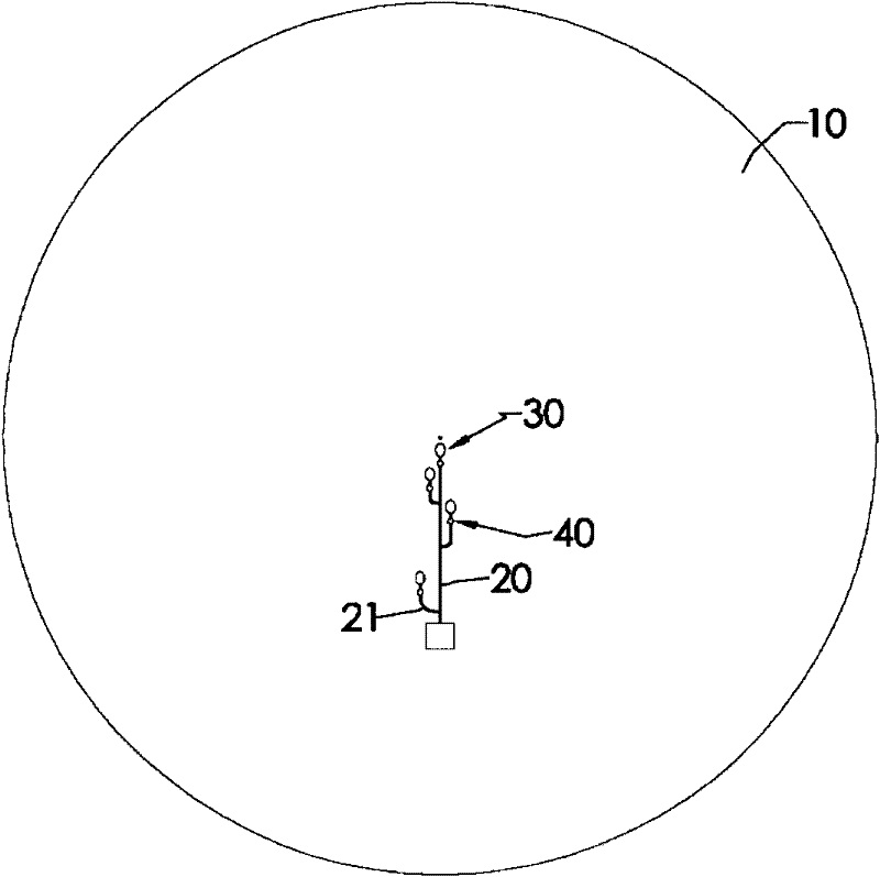
[0060] In the main body 10, a capillary valve 40 is arranged every 0.5cm radius, and then a capillary valve 40 is arranged every 0.4cm; the valve width of each capillary valve 30 is a capillary valve of 200 μm. Figure 5 is the relationship between the radial position of the capillary valve and the breakthrough speed. From this result, it can be seen that in the range of the smaller radius position (0 to 1.5cm), there is a significant difference between the breakthrough rotational speed of each capillary valve 40; in the range of the larger radius position (2.0 to 4.5cm), the The difference between the breakthrough rotational speeds of the capillary valve 40 gradually decreases as the radius increases, and there is even a phenomenon that the breakthrough rotational speeds overlap.

[0061] 2. Comparison of breakthrough speed of capillary val...


PUM


Abstract

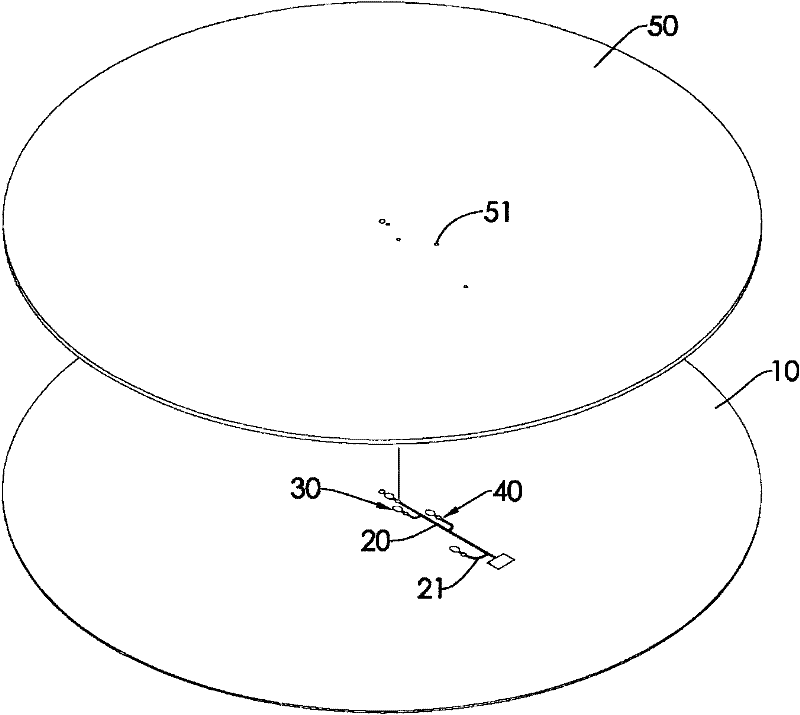
The invention relates to a centrifugal type microfluidic device which comprises a body, a plurality of storage tanks, a plurality of passage ways and a plurality of capillary valves, wherein the body is a disk-shaped disc; each storage tank is formed on the disc and is communicated with the corresponding passage way; and the capillary valves are arranged at joints between the passage ways and thestorage tanks. By means of the capillary valves arranged at positions near the circle center of the body, the breakthrough rotating speed of the capillary valves is increased, the operating space of the rotating speed is increased, and the effect that each capillary valve can sequentially release fluid is fully achieved.

Description

technical field [0001] The present invention relates to a microfluidic device, in particular to a centrifugal microfluidic device that controls fluid release through the interaction of centrifugal force and surface tension in a capillary valve. Background technique [0002] With the advancement of semiconductor and MEMS technology, the application of biological analysis and biomedical testing is gradually developing towards miniaturization, high sensitivity, high precision and rapid automatic analysis and detection technology; micro total analysis systems (micro total analysis systems, μTAS ) concept was proposed in the early 1990s. From sample pretreatment, chemical reaction, analyte separation and purification, to analyte detection and data analysis, all steps can be carried out in μTAS to become a complete chemical analysis process. The development and growth of medicine, medicine, biotechnology and environmental monitoring all require a large amount of chemical analysis...

Claims


Application Information

Patent Timeline
IPC IPC(8): B01J19/00G01N35/00
Inventor 施志欣吴和晋颜志宏陈文豪范康洋洪瑞彬
Owner AMPOC FAR EAST CO LTD
Learn More