Separator

A separator and eddy current separation technology, applied in the field of separators, can solve the problems of waste of resources, mediocre beneficiation effect, unusable resources, etc., to achieve the effect of eliminating nitrogen oxide emissions, solving water resource pollution, and solving water resource shortages

A separator and eddy current separation technology, applied in the field of separators, can solve the problems of waste of resources, mediocre beneficiation effect, unusable resources, etc., to achieve the effect of eliminating nitrogen oxide emissions, solving water resource pollution, and solving water resource shortages

CN102441501AInactive Publication Date: 2012-05-09ι™ˆδΉ…ζ–Œ

Image

  • Separator
  • Separator
  • Separator

Examples


Embodiment Construction

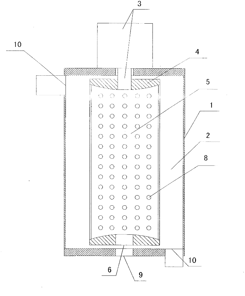
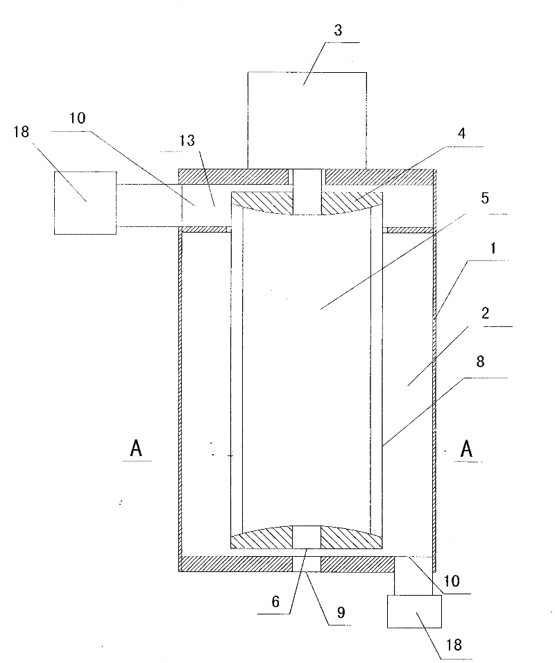
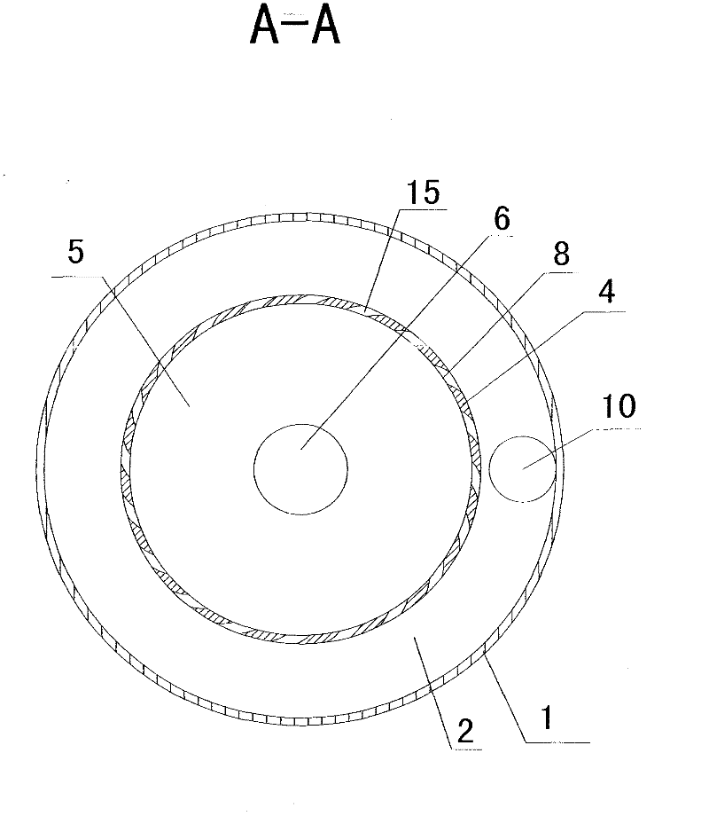
[0036] The main structure of the separator of the present invention includes a housing 1, at least one housing chamber 2 is arranged in the housing 1, a transmission device 3 is installed on the housing 1, a vortex separation cylinder 4 is arranged in the housing chamber 2, the transmission device 3 and the eddy current separation cylinder 4 Connection, the vortex separation cylinder 4 is provided with a vortex separation chamber 5, one end of the vortex separation chamber 5 is provided with a fluid inlet 6, and a plurality of vortex separation chamber outlets 8 are arranged on the outer periphery of the vortex separation chamber 5, and the shell cavity inlet 9 is set corresponding to the fluid inlet 6, and the shell cavity 2 At least two housing chamber outlets 10 are provided.

[0037] The scope of the casing 1 includes a base, a casing, and a power unit, and each part can be collectively referred to as a casing. The housing can also be integrated with the power device to fo...


PUM


Abstract

A separator comprises a casing; at least one casing cavity is arranged in the casing; a driving device is mounted on the casing; a vortex separating cylinder is arranged in the casing cavity; the driving device is connected with the vortex separating cylinder; a vortex separating chamber is arranged in the vortex separating cylinder; a fluid inlet is formed at one end of the vortex separating chamber; a plurality of vortex separating chamber outlets are formed on the periphery of the vortex separating chamber; a casing cavity inlet corresponds to the fluid inlet; and the casing cavity is provided with at least two casing cavity outlets. The separator can achieve the separation of fluid from vortex through adopting a brand-new separating principle and a brand-new separating method, making the best of the circular motion and the fluid motion, and utilizing vortex with the rotating speed progressively increased from the center to the periphery. The separator can be widely used in the fields such as sewage disposal, dust removal, dust absorption, garbage disposal, powder concentrating, mineral separation, seawater desalination, ocean chemical engineering, oxygen production, hydrogen production, nano material manufacturing, harmful gas resolving treatment, refrigeration, reactors, oil refining, metallurgy and the like, can provide clean energy, solves the energy problem and the environment pollution problem, and can thoroughly create an environment of blue sky, white cloud and clear water.

Description

technical field [0001] The present invention relates to separator equipment, centrifuge equipment, sewage treatment equipment, seawater desalination equipment, marine chemical equipment, mineral processing equipment, garbage treatment equipment, hydrogen production equipment, carbon dioxide decomposition treatment equipment, harmful gas decomposition treatment equipment, nano material manufacturing equipment, Reactor equipment, air purification equipment, dust removal equipment, vacuum equipment, air conditioning, refrigeration equipment, oxygen production equipment and other fields, specifically a separator. Background technique [0002] Today's environmental pollution mainly includes water pollution, air pollution, garbage pollution, refrigerant damage to the ozone layer, and greenhouse gas emissions. The existing sewage treatment equipment is complicated, the cost is too high, the cost of sewage treatment is too high, and the treatment effect is mediocre. Sewage treatment...

Claims


Application Information

Patent Timeline
09 May 2012
Publication
CN102441501A
IPC
B04B5/00; B04B7/02
Inventors
ι™ˆδΉ…ζ–Œ