Method for manufacturing electronic device shell

A technology for electronic devices and manufacturing methods, applied in the direction of coating, etc., can solve the problems of long cycle time and difficulty in controlling the degree of deformation of finished products.

Active Publication Date: 2012-05-09
QUANTA COMPUTER INC
View PDF6 Cites 13 Cited by
  • Summary
  • Abstract
  • Description
  • Claims
  • Application Information

AI Technical Summary

Problems solved by technology

[0003] For the background of the existing embedded injection molding on metal parts, since the mold is often maintained at a high mold temperat

Method used


Image

  • Method for manufacturing electronic device shell
  • Method for manufacturing electronic device shell
  • Method for manufacturing electronic device shell

Examples


Embodiment Construction

[0037] The following will clearly illustrate the spirit of the present invention with illustrations and detailed descriptions. After those skilled in the art understand the embodiments of the present invention, they can be changed and modified by the technology taught in the present invention, which does not depart from the present invention. spirit and scope.

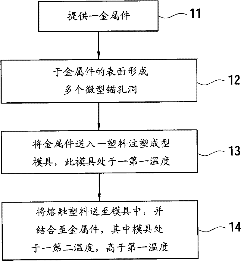
[0038] see figure 1 as shown, figure 1 A flow chart of an embodiment of the manufacturing method of the housing of the electronic device according to the present invention is shown. The manufacturing method of the electronic device housing of the present invention includes the following steps:

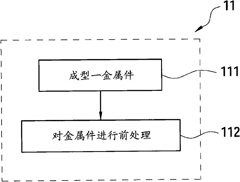
[0039] Step 11 provides a metal piece. Step 12 forms a plurality of micro-anchor holes on the surface of the metal piece. Step 13 Sending the metal part into a plastic injection molding mold, wherein the plastic injection molding mold is at a first temperature. Step 14: Sending a molten plastic to a plastic injection moldi...


PUM

PropertyMeasurementUnit
Apertureaaaaaaaaaa

Abstract

The invention discloses a method for manufacturing an electronic device shell, which comprises the following steps of: providing a metal piece, forming a plurality of micro anchoring holes on the surface of the metal piece, and putting the metal piece in a plastic injection moulding and forming mould, wherein the plastic injection moulding and forming mould is at first temperature; feeding molten plastic into the plastic injection moulding and forming mould, and ejecting and bonding the molten plastic to the surface of the metal piece, wherein the plastic injection moulding and forming mould is at second temperature; and the second temperature is higher than the first temperature.

Description

technical field [0001] The invention relates to a method for manufacturing a casing, in particular to a method for manufacturing an electronic device casing. Background technique [0002] At present, the combination methods of metal parts and plastic parts on the casing of electronic devices mainly include structural locking screw method; plastic structure hot-melt method, coating adhesive bonding, embedding and injection molding on metal parts and so on. [0003] For the background of the existing embedded injection molding of metal parts, since the mold is often maintained at a high mold temperature, the cycle time of plastic part molding will be too long and the degree of deformation of the finished product will be difficult to control. Contents of the invention [0004] In order to overcome the above problems, the present invention replaces the existing common gluing and pasting technology. The metal parts and plastic parts are integrally formed by injection molding of...

Claims


Application Information

Patent Timeline
IPC IPC(8): B29C45/14B29C45/78
Inventor 林淑真
Owner QUANTA COMPUTER INC
Why Eureka
Try Eureka