Vehicular charger and battery cooling structure

A charger and battery technology, which is applied to the arrangement of the cooling combination of the power unit, vehicle components, power units, etc., can solve problems such as the performance degradation of the charger or battery, and achieve the effects of space saving, low cost, and protection from moisture erosion.

Inactive Publication Date: 2012-05-09
SHIN MEIWA IND CO LTD
View PDF3 Cites 4 Cited by
  • Summary
  • Abstract
  • Description
  • Claims
  • Application Information

AI Technical Summary

Problems solved by technology

On the other hand, since the charger generates heat during voltage conversion, the inside of the storage box becomes high temperature, which may cause the performance of the charger or the battery to deteriorate.

Method used


Image

  • Vehicular charger and battery cooling structure
  • Vehicular charger and battery cooling structure
  • Vehicular charger and battery cooling structure

Examples


Embodiment Construction

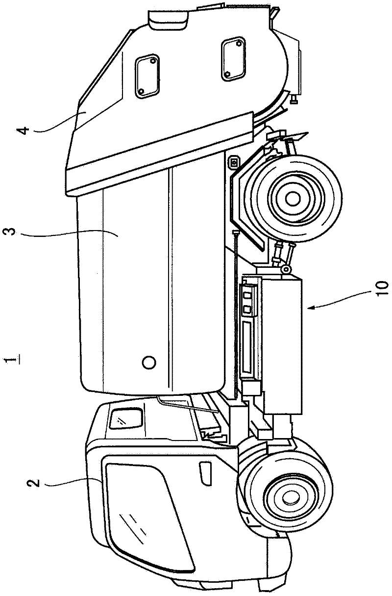
[0039] use Figure 1 to Figure 3 , and an embodiment in the case where the present invention is applied to a garbage collection vehicle will be described.

[0040] Such as figure 1 As shown, in the garbage collection vehicle 1 of this embodiment, the driver's cab 2, the garbage storage box 3, and the garbage input box 4 with a loading device not shown in the figure are mounted on the side of the vehicle in the order from the front side of the vehicle to the rear side. on the frame that extends in the fore-and-aft direction of the vehicle.

[0041]In addition, on the frame, a storage box 10 is supported below the garbage storage box 3, and devices for operating actuators of operating equipment such as the operation of the loading device and the opening and closing of the garbage storage box 4 are accommodated in the storage box 10. .

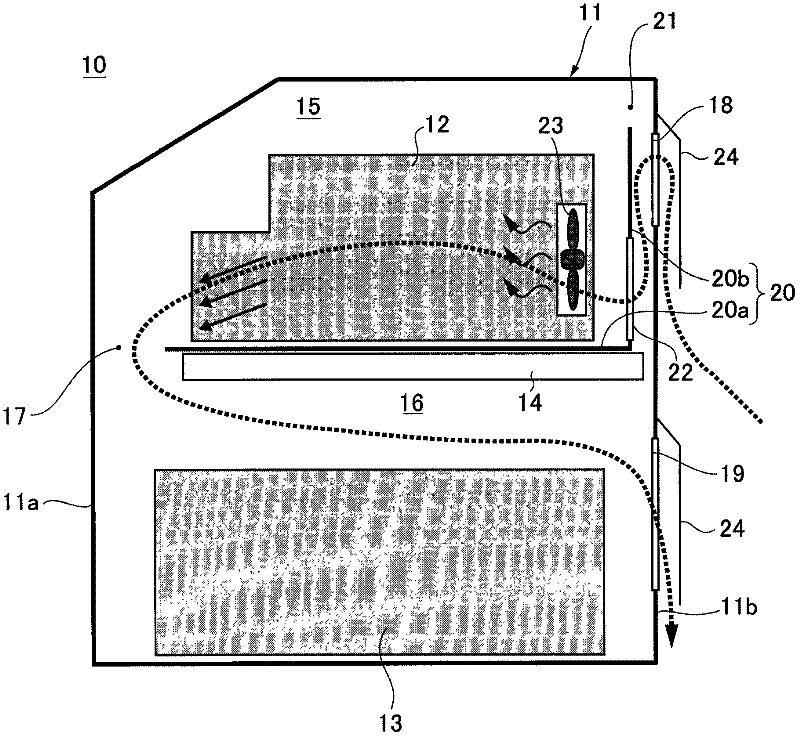
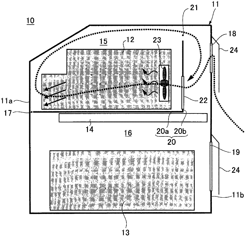
[0042] figure 2 It is a figure which schematically shows the installation structure of the apparatus accommodated in the storage box 10. FI...


PUM


Abstract

The present invention provides a cooling structure which can perform most appropriate cooling on a charger or a battery that is carried on the vehicle corresponding to a use environment. The cooling structure is provided with the following components: a charger accommodating chamber (15) which accommodates the charger (12); a leading-in opening (18) which sucks outer air into the charger accommodating chamber (15); a battery accommodating chamber (16) which accommodates the battery (13) and is communicated with the charger accommodating chamber (15) through a communication part (17); and a discharge opening (19) which discharges air from the battery accommodating chamber (16). A sliding component (20) which supports the charger (12) is set to slidable in the charger accommodating chamber (15), and communication opening of the communication part (17) can be adjusted corresponding to the sliding position.

Description

technical field [0001] The present invention relates to a structure for cooling a charger and a battery mounted on a vehicle. Background technique [0002] Currently, vehicles equipped with chargers or batteries are widely known. In such a vehicle, the charger or the battery is usually stored in a storage box so that the charger or the battery will not be exposed to rain or the like. On the other hand, since the charger generates heat during voltage conversion, the inside of the storage box becomes high temperature, which may cause performance degradation of the charger or battery. Therefore, in the vehicles disclosed in Patent Documents 1 to 3, air is sucked in by a cooling fan to forcibly cool the inside of the storage box. [0003] Patent Document 1: Japanese Patent Laid-Open No. 2008-80930 [0004] Patent Document 2: Japanese Patent Laid-Open No. 2005-138792 [0005] Patent Document 3: Japanese Patent Laid-Open No. 2009-262759 Contents of the invention [0006] Ho...

Claims


Application Information

Patent Timeline
Patent Type & Authority Applications(China)
IPC IPC(8): B60K11/06
Inventor 大久保优介
Owner SHIN MEIWA IND CO LTD
Why Eureka
Try Eureka