Defoamer and defoaming method thereof

A defoaming machine and defoaming technology, applied in chemical instruments and methods, mixers, dissolving, etc., can solve problems such as difficult to attract bubbles

Active Publication Date: 2012-05-09
MITSUBISHI HEAVY IND ENVIRONMENTAL & CHEM ENG CO LTD
View PDF4 Cites 15 Cited by
  • Summary
  • Abstract
  • Description
  • Claims
  • Application Information

AI Technical Summary

Problems solved by technology

[0007] However, in this example, the attractive force of the air bubbles depends on the structure of the rotor rotating at high speed, and the air bubble suction port itself has no attractive force
For such suction based on air flow, in the case of air bubbles with high viscosity, etc., a strong air flow is required in order to improve the reliability of suction. Difficult to attract air bubbles effectively

Method used


Image

  • Defoamer and defoaming method thereof
  • Defoamer and defoaming method thereof
  • Defoamer and defoaming method thereof

Examples


no. 1 approach

[0059] Hereinafter, the defoaming machine and the defoaming method according to the first embodiment of the present invention will be described in detail with reference to the drawings.

[0060] First, the structure of the defoaming machine according to the first embodiment of the present invention will be described in detail.

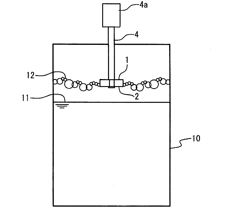
[0061] image 3 It is a longitudinal sectional view which shows an example of the state which attached the defoaming machine in embodiment of this invention to a water tank. refer to image 3 , the main defoaming vane 20 and the suction port 21 of this embodiment are provided so as to be located between the liquid surface 11 in the water tank 10 and the air bubble surface 12 formed on the upper part. The suction port 21 is provided on the liquid surface side of the main defoaming vane 20, and the rotating shaft 4 of the driving machine 4a, such as an underwater motor which is a rotation drive mechanism, is connected to the opposite side. The rotatio...

no. 2 approach

[0101] Hereinafter, a defoaming machine and a defoaming method according to a second embodiment of the present invention will be described in detail with reference to the drawings.

[0102] First, the structure of the defoamer of 2nd Embodiment of this invention is demonstrated in detail.

[0103] 11 is a perspective view showing an example of the structure of the defoaming blade of the defoaming machine according to the second embodiment of the present invention, Figure 11A is its top view, Figure 11B is its side view. refer to Figure 11A , the main defoaming vane of the present embodiment further includes a partition plate 31 in addition to the main defoaming vane of the first embodiment. The partition plate 31 has a shape similar to that of the plate-shaped body 1 and the plate-shaped body 2 . The partition plate 31 is in contact with the respective partition plates 3 on the rear side in the direction of travel and on the centrifugal side when the main defoaming blad...

no. 3 approach

[0114] Hereinafter, a defoaming machine and a defoaming method according to a third embodiment of the present invention will be described in detail with reference to the drawings.

[0115] First, the structure of the defoamer of the 3rd embodiment of this invention is demonstrated in detail.

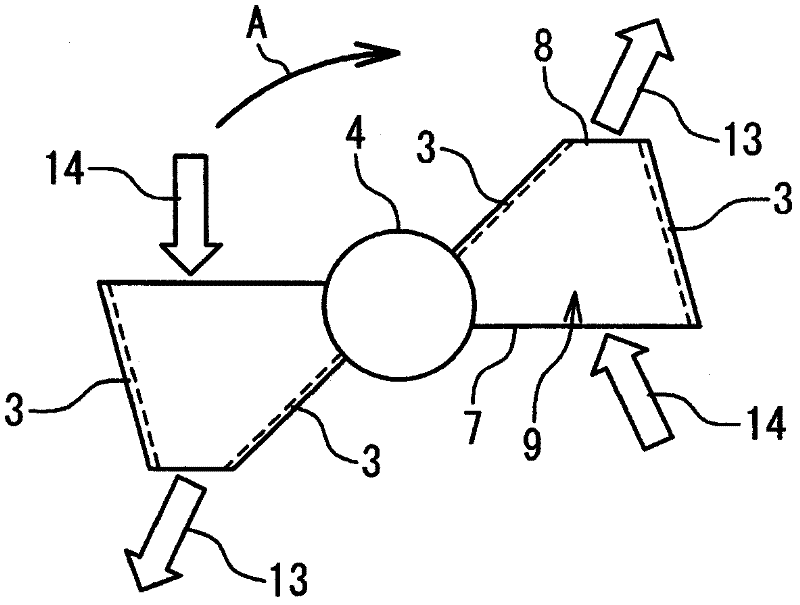
[0116] Figure 12 It is a sectional view which shows an example of the structure of the defoaming blade|wing of the defoaming machine in 3rd Embodiment of this invention. refer to Figure 12 , in the defoaming vane of this embodiment, the guide vane 32 is provided in the inner region 26 of the suction port 21 . The guide vane 32 functions as an impeller (vane wheel) in a pump as the suction port 21 rotates. The direction of the flow generated by the guide vanes 32 is the flow direction 27 of air bubbles at the inner surface 24 of the suction port 21 from the narrow-mouth-side opening 22 toward the wide-mouth-side opening 23 .

[0117] exist Figure 12 In the figure above, two plate-...


PUM


Abstract

The present invention provides a defoamer which can effectively defoam no matter nature, state and stacking state of foams, and a defoaming method thereof. The defoamer comprises the following components: a rotation driving mechanism (4a), a hollow-structure main defoaming blade (20) which is equipped on a rotating shaft (4) of the rotation driving mechanism (4a), and a suction opening. The suction opening is provided with a narrow-mouth side opening (22) which sucks into bubbles and a wide-mouth side opening (23) that supplies bubbles to the main defoaming blade (20). The periphery of the wide-mouth side opening (23) is connected with the main defoaming blade (20). The section area of the suction opening narrows in a direction of departing from the main defoaming blade (20). The main defoaming blade (20) is provided with an inflow opening (7) and a discharging opening (8), wherein, the front end of the inflow opening (7) in advancing direction causes the bubbles to flow into the hollow structure in rotation. The area of the discharging opening (8) is smaller than that of the inflow opening (7). Furthermore the bubbles are discharged out of the hollow structure at a back position in the advancing direction, which is closer to the centrifugal direction.

Description

technical field [0001] The invention relates to a defoaming machine and a defoaming method. Background technique [0002] In the activated sludge method used for purification of waste water treatment facilities including excrement, dirty water, etc., aeration is performed by blowing oxygen into the waste water, and at this time, air bubbles are generated in the upper part of the waste water. Wastewater, especially excrement, contains a high-viscosity polymer compound that promotes foaming, so it is easy to foam when aerated, and a large number of bubble layers are formed. In addition, when treating wastewater without a dilution effect, highly viscous air bubbles generated in large quantities are not easy to disappear, and it is necessary to take antifoaming measures. [0003] In connection with the above description, Japanese Patent No. 2781751 discloses a defoaming device. Figure 1A and Figure 1B It is a perspective view for explaining the structure of the defoaming van...

Claims


Application Information

Patent Timeline
IPC IPC(8): C02F1/20B01F33/40
Inventor 代田博文松田友纪长克美
Owner MITSUBISHI HEAVY IND ENVIRONMENTAL & CHEM ENG CO LTD
Why Eureka
Try Eureka