Defoamer and defoaming method thereof
A defoaming machine and defoaming technology, applied in chemical instruments and methods, mixers, dissolving, etc., can solve problems such as difficult to attract bubbles
- Summary
- Abstract
- Description
- Claims
- Application Information
AI Technical Summary
Problems solved by technology
Method used
Image
Examples
no. 1 approach
[0059] Hereinafter, the defoaming machine and the defoaming method according to the first embodiment of the present invention will be described in detail with reference to the drawings.
[0060] First, the structure of the defoaming machine according to the first embodiment of the present invention will be described in detail.
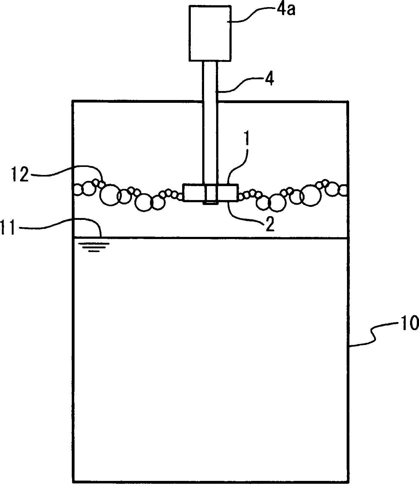
[0061] image 3 It is a longitudinal sectional view which shows an example of the state which attached the defoaming machine in embodiment of this invention to a water tank. refer to image 3 , the main defoaming vane 20 and the suction port 21 of this embodiment are provided so as to be located between the liquid surface 11 in the water tank 10 and the air bubble surface 12 formed on the upper part. The suction port 21 is provided on the liquid surface side of the main defoaming vane 20, and the rotating shaft 4 of the driving machine 4a, such as an underwater motor which is a rotation drive mechanism, is connected to the opposite side. The rotatio...
no. 2 approach
[0101] Hereinafter, a defoaming machine and a defoaming method according to a second embodiment of the present invention will be described in detail with reference to the drawings.
[0102] First, the structure of the defoamer of 2nd Embodiment of this invention is demonstrated in detail.
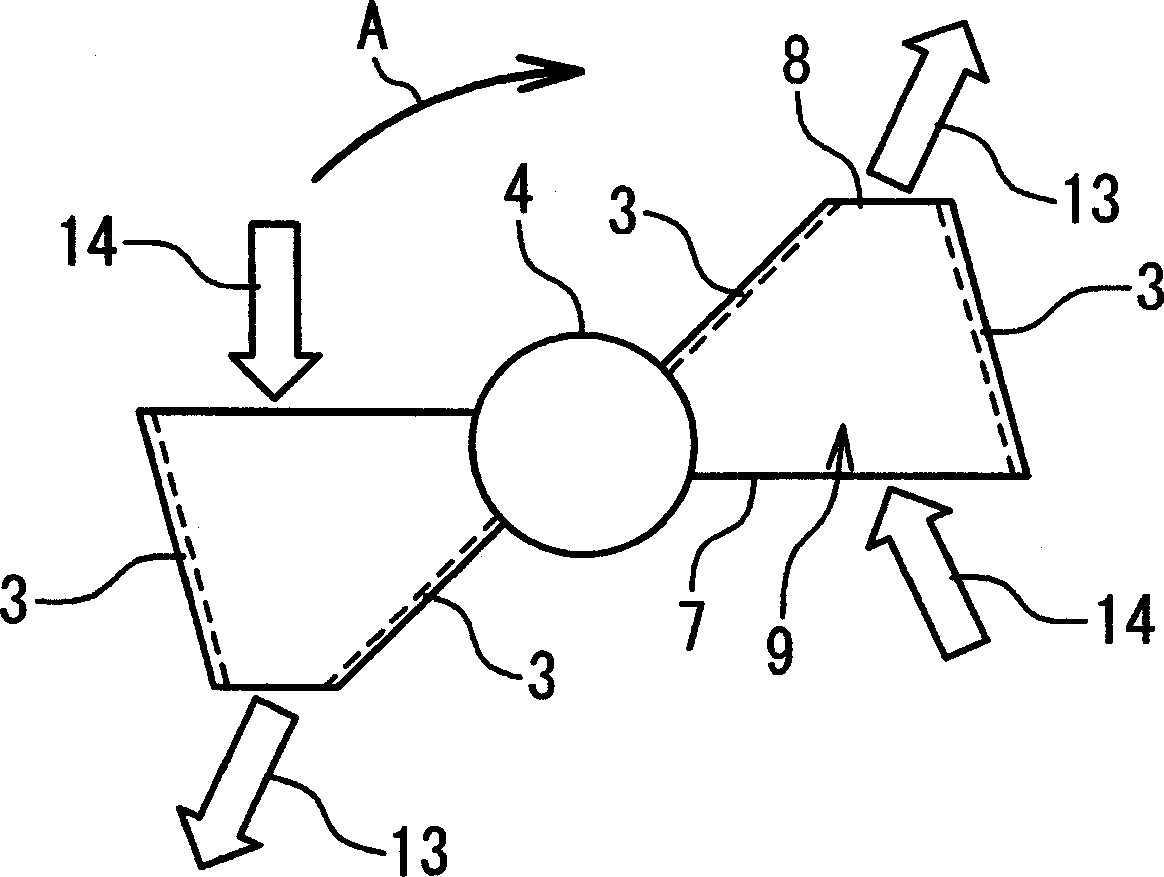
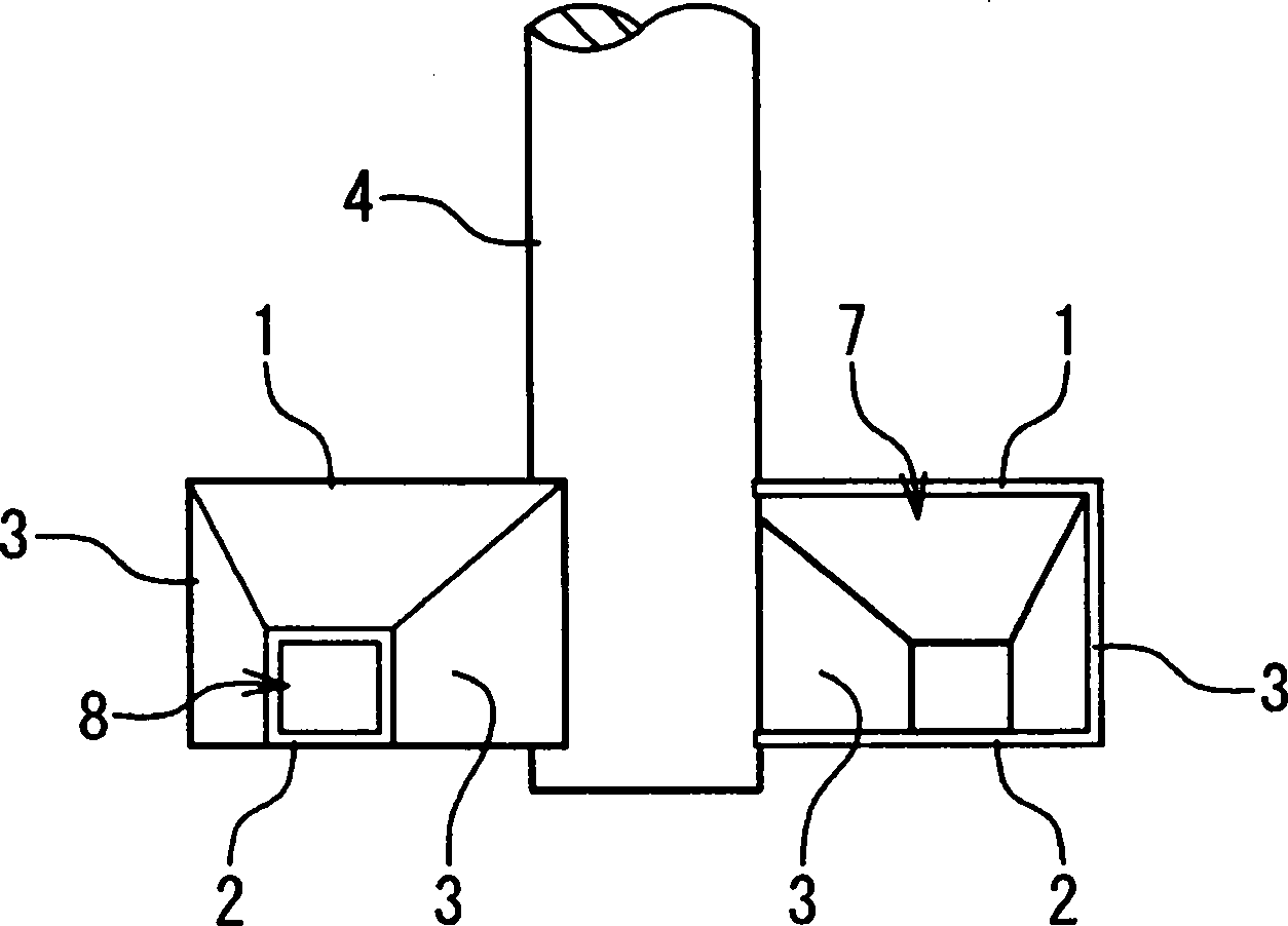
[0103] 11 is a perspective view showing an example of the structure of the defoaming blade of the defoaming machine according to the second embodiment of the present invention, Figure 11A is its top view, Figure 11B is its side view. refer to Figure 11A , the main defoaming vane of the present embodiment further includes a partition plate 31 in addition to the main defoaming vane of the first embodiment. The partition plate 31 has a shape similar to that of the plate-shaped body 1 and the plate-shaped body 2 . The partition plate 31 is in contact with the respective partition plates 3 on the rear side in the direction of travel and on the centrifugal side when the main defoaming blad...
no. 3 approach
[0114] Hereinafter, a defoaming machine and a defoaming method according to a third embodiment of the present invention will be described in detail with reference to the drawings.
[0115] First, the structure of the defoamer of the 3rd embodiment of this invention is demonstrated in detail.
[0116] Figure 12 It is a sectional view which shows an example of the structure of the defoaming blade|wing of the defoaming machine in 3rd Embodiment of this invention. refer to Figure 12 , in the defoaming vane of this embodiment, the guide vane 32 is provided in the inner region 26 of the suction port 21 . The guide vane 32 functions as an impeller (vane wheel) in a pump as the suction port 21 rotates. The direction of the flow generated by the guide vanes 32 is the flow direction 27 of air bubbles at the inner surface 24 of the suction port 21 from the narrow-mouth-side opening 22 toward the wide-mouth-side opening 23 .
[0117] exist Figure 12 In the figure above, two plate-...
PUM
 Abstract
Description
Claims
Application Information
 - R&D
- Intellectual Property
- Life Sciences
- Materials
- Tech Scout
- Unparalleled Data Quality
- Higher Quality Content
- 60% Fewer Hallucinations
Browse by: Latest US Patents, China's latest patents, Technical Efficacy Thesaurus, Application Domain, Technology Topic, Popular Technical Reports.
© 2025 PatSnap. All rights reserved.Legal|Privacy policy|Modern Slavery Act Transparency Statement|Sitemap|About US| Contact US: help@patsnap.com


