Vertical shaft blower or wind driven generator

A wind turbine, vertical axis technology, applied in the fields of wind energy utilization, wind machinery and wind power generation, to achieve the effect of eliminating resonance

Inactive Publication Date: 2012-05-09
孟英志
View PDF10 Cites 4 Cited by
  • Summary
  • Abstract
  • Description
  • Claims
  • Application Information

AI Technical Summary

Problems solved by technology

[0014] Another technical problem to be solved by the present invention is to provide a vertical axis fan or wind power generator that solves the problem of "the moment of work done is not the same at different rotational angle positions".

Method used


Image

  • Vertical shaft blower or wind driven generator
  • Vertical shaft blower or wind driven generator
  • Vertical shaft blower or wind driven generator

Examples


Embodiment 1

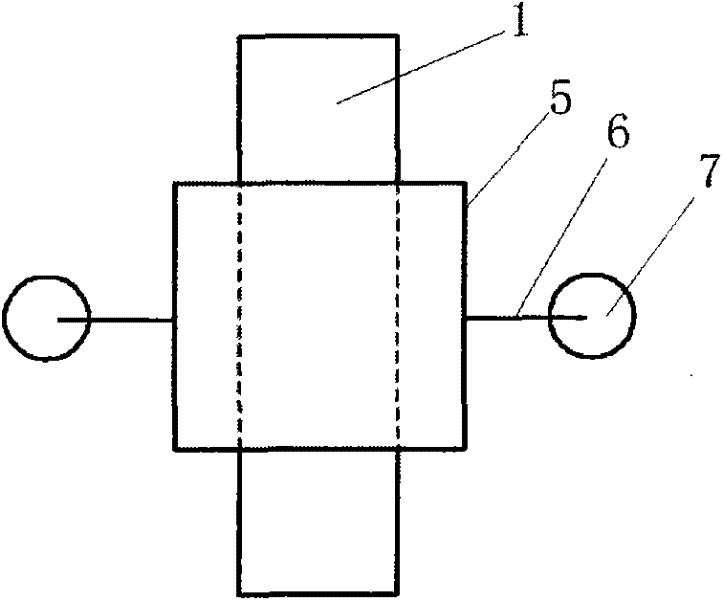
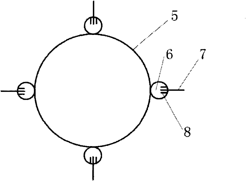
[0094] figure 1 It is a front view schematic diagram of a structural principle of the movable connector of the present invention; the shaft sleeve 5 is fastened to the main shaft or the transmission shaft, and a ring-shaped object 6 is fixedly installed on the shaft sleeve 5, and the ring-shaped object 6 is transversely Or installed vertically, the ring-shaped object 6 is set with a ring-shaped object 7, the ring-shaped object 7 is installed vertically or horizontally, and there are two baffles 8 in the ring-shaped object 6, the baffles 8 can limit the ring-shaped object 7 Moving horizontally, the ring-shaped object 7 can move up and down around the ring-shaped object 6; the ring-shaped object 7 is fixedly connected to the wind wheel or the connecting rod of the wind wheel; the ring-shaped object can be a circular ring or an elliptical ring or a rectangular ring or Any ring-shaped object; the embodiment of the present invention selects a ring.

[0095] figure 2 It is a sch...

Embodiment 2

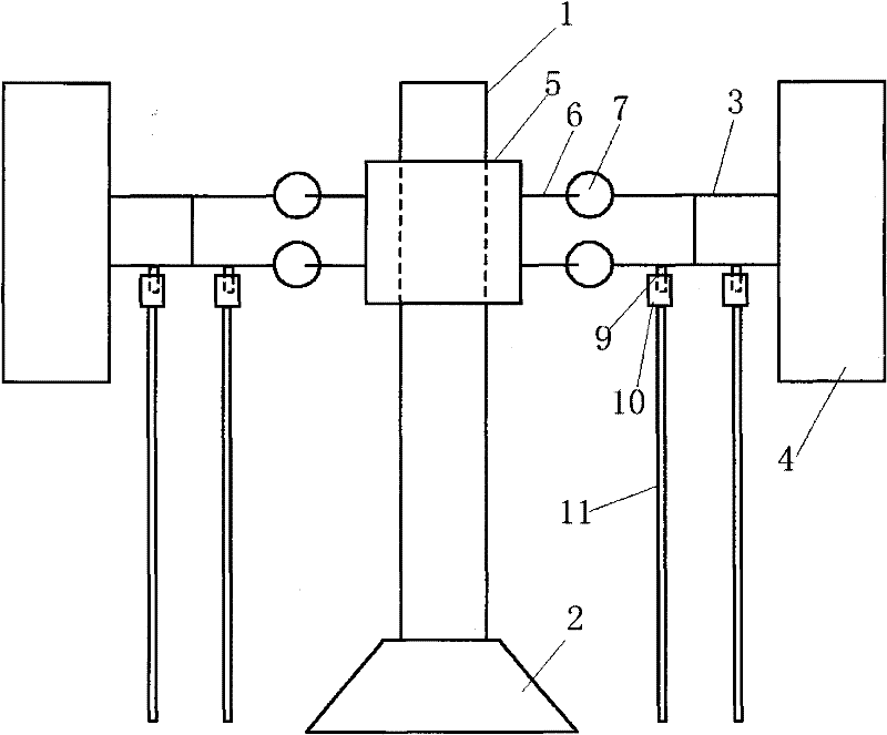
[0105] Figure 5 It is a schematic plan view of a structural principle of the movable connector of the present invention; the bushing 5 is fastened to the main shaft or the transmission shaft, and a connecting rod 13 is fixedly installed on the bushing 5, and one end of the connecting rod 13 is fixedly connected On the shaft sleeve 5, there is a movable shaft 14 at the other end, the movable shaft 14 is fixedly installed in the connecting rod 13 through the bearing 15, the movable shaft 14 can rotate freely in the bearing 15; the movable shaft 14 is fixedly connected to the connecting rod 3 of the wind wheel or wind wheel;

[0106] When the wind wheel or the wind wheel connecting rod rotates around the main shaft or the transmission shaft under the action of wind force, the wind wheel connecting rod drives the connecting rod 13 and the main shaft or the transmission shaft to rotate together to drive the generator to generate electricity; when the wind wheel or the wind wheel c...

Embodiment 3

[0111] Such as Figure 8 , Figure 9 , Figure 10 as shown, Figure 8 It is a schematic diagram of the top view of the double-link structure, Figure 9 It is a schematic diagram of the top view of the single-link structure, Figure 10 for Figure 8 or Figure 9 The schematic diagram of the front view;

[0112] It includes a shaft sleeve 5, a connecting rod 13, a movable shaft 14, and a bearing 15; it is characterized in that: the shaft sleeve 5 is tightly connected to the main shaft or the transmission shaft, and a connecting rod 13 is fixedly installed on the shaft sleeve 5, and the connecting rod 13 One end of the shaft sleeve 5 is fixedly connected, and the other end has a movable shaft 14, which is fixedly installed in the connecting rod 13 through a bearing 15, and the movable shaft 14 can rotate freely in the bearing 15; the movable shaft 14 is connected to the connecting rod 13 -1, the movable shaft 14-1 and the bearing 15-1, the movable shaft 14-1 is connected t...


PUM


Abstract

The invention discloses a vertical shaft blower or a wind driven generator. The vertical shaft blower or the wind driven generator is characterized in that a main shaft or a transmission shaft is movably connected with a wind wheel to successfully solve the longstanding problem influencing the further development of the vertical shaft wind driven generator that resonance is easily caused by the main shaft. In the invention, through adopting a vibration reduction sleeve, the longstanding problem influencing the further development of the vertical shaft wind driven generator that the output power fluctuates caused by different acting moments at different corners can be successfully solved.

Description

1. Technical field [0001] The invention belongs to the technical field of wind energy utilization, and is especially applicable to the technical fields of wind power machinery and wind power generation. 2. Background technology [0002] Although the technology of the horizontal axis propeller wind turbine is now very mature, a lot of experience has been accumulated, and the research is very detailed, the horizontal axis propeller wind turbine is not the best wind turbine. The research results show that the vertical axis wind turbine In many places, it has more advantages than horizontal-axis propeller wind turbines. For example, vertical-axis wind turbines have many advantages such as high power generation efficiency, convenient maintenance, and low investment costs. important direction. [0003] Although vertical-axis fans have obvious advantages compared with horizontal-axis fans, in fact, horizontal-axis fans are mainly used for wind power generation at present. The reas...

Claims


Application Information

Patent Timeline
Patent Type & Authority Applications(China)
IPC IPC(8): F03D9/00F03D3/00F03D3/06F16F15/22
CPCF05B2260/96F03D3/062F05B2240/60F03D3/005Y02E10/74Y02P70/50
Inventor 孟英志
Owner 孟英志
Why Eureka
Try Eureka