Disk spring

A disc spring and reed technology, applied in the field of springs, can solve the problems of insufficient damping ratio and complex structure, and achieve the effects of simplifying the structure, eliminating resonance and reducing noise.

Inactive Publication Date: 2006-05-24
尹学军
View PDF0 Cites 6 Cited by
  • Summary
  • Abstract
  • Description
  • Claims
  • Application Information

AI Technical Summary

Problems solved by technology

In practice, in order to increase its damping, it is sometimes used to cover the whole surface of the spring helical body with a layer of rubber tube, but rubber is fundamentally a viscoelastic material. The vibration and noise will have a certain damping effect. For most mechanical vibrations, the damping ratio is only 1-3%. When used in parallel with the spring, the damping ratio is even smaller. In most cases, the damping ratio is far from enough. For example, for the vibration reduction and vibration isolation of general vehicles and equipment, the damping ratio is required to be between 10% and 30%. At this time, it must be used with additional damping devices, which makes the structure complicated.

Method used


Image

  • Disk spring
  • Disk spring
  • Disk spring

Examples


Embodiment 1

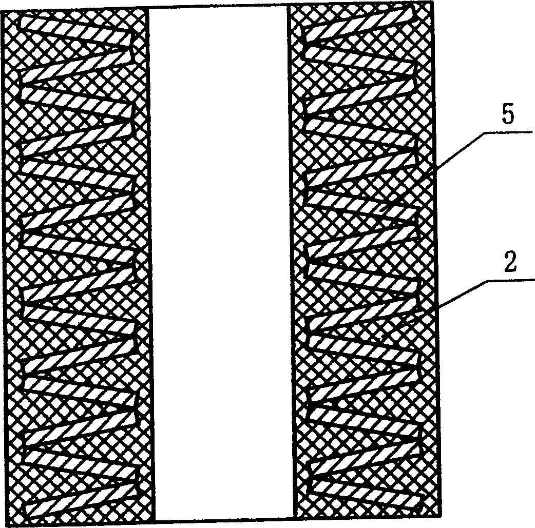
[0016] see figure 1 The disc spring group 5 composed of multiple disc springs is all embedded in the tubular damping body 2. When the coiled spring deforms, it will shear and squeeze the damping body 2. Since the damping body 2 is hollow, it is easy to deform.

[0017] The damping body is high damping modified asphalt which is solid (viscoplastic) at room temperature. When the disc spring is deformed by force, the damping body is deformed by force at the same time. Since the damping material has a large internal friction, it will always produce a damping force that is always opposite to the direction of motion. Therefore, the spring with this structure has a large damping ratio.

Embodiment 2

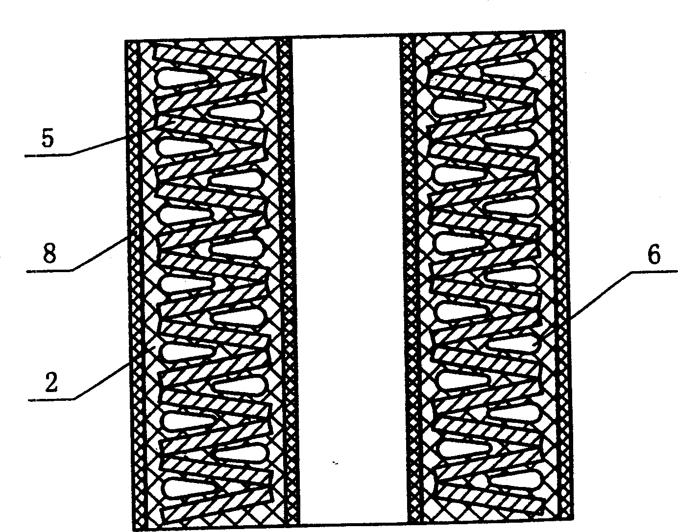
[0019] see figure 2 , the disc spring group 5 composed of a plurality of disc springs is integrally embedded in the tubular damping body 2, and there is an annular cavity 6 between the reeds, so the damping body is more susceptible to shear deformation and has a more Good linear stiffness and damping ratio. There is also a layer of elastic material on the inner and outer surfaces of the damping body as a restraint protection layer 8, which can help the damping material reset more completely when unloaded, and protect the damping material from the friction of the guide column and the impact of external force.

Embodiment 3

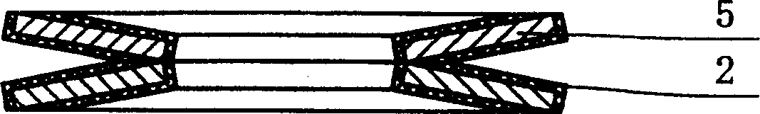
[0021] image 3 As shown, the disc spring 5 is single-piece embedded in the hollow damping body 2, and its cross-sectional shape is roughly concentrically similar to that of the reed, except that there is no damping body in the contact area of ​​the disc spring to prevent the damping body from being partially squeezed Destruction or extrusion permanent deformation. This embodiment does not greatly change the linearity of the spring, and is suitable for occasions where the damping requirement is not too high but the linearity requirement is high. Due to the implementation of a single piece, it can be mass-produced. The damping body should be suitable for high-efficiency and mass production, such as damping materials that can be sprayed, dipped, coated or poured, such as high-damping polyurethane.


PUM


Abstract

This invention relates to a spring, which contains spring body and damp unit having high damping material. When spring vibrates by external force, the amp unit is deformed and generating great inner friction to convert vibration energy into heat energy, which reduces and eliminates vibration and noise.

Description

technical field [0001] The present invention belongs to springs. This application is a divisional application of No. 03112550.6 patent application for invention, the original filing date is June 11, 2003, and the title of the invention is spring. Background technique [0002] Ordinary springs are made of pure elastic materials, and their damping is very small, especially metal springs. In practice, in order to increase its damping, it is sometimes used to cover the whole surface of the spring helical body with a layer of rubber tube, but rubber is fundamentally a viscoelastic material. The vibration and noise will have a certain damping effect. For most mechanical vibrations, the damping ratio is only 1-3%. When used in parallel with the spring, the damping ratio is even smaller. In most cases, the damping ratio is far from enough. For example, for the vibration reduction and vibration isolation of general vehicles and equipment, the damping ratio...

Claims


Application Information

Patent Timeline
Patent Type & Authority Applications(China)
IPC IPC(8): F16F3/00F16F3/12
CPCF16F3/12
Inventor 尹学军
Owner 尹学军
Why Eureka
Try Eureka