Processing technology of speaker frame with precisely punched riveting holes and mounting holes

A loudspeaker pot frame and processing technology, applied in the direction of sensors, electrical components, etc., can solve the problems of low dimensional control accuracy, small area occupied by positioning holes and riveting holes, difficult positioning of positioning holes and riveting holes, etc.

A loudspeaker pot frame and processing technology, applied in the direction of sensors, electrical components, etc., can solve the problems of low dimensional control accuracy, small area occupied by positioning holes and riveting holes, difficult positioning of positioning holes and riveting holes, etc.

CN104038883AInactive Publication Date: 2014-09-10WUZHOU HENGSHENG ELECTRONICS

Image

  • Processing technology of speaker frame with precisely punched riveting holes and mounting holes
  • Processing technology of speaker frame with precisely punched riveting holes and mounting holes

Examples


Embodiment 1

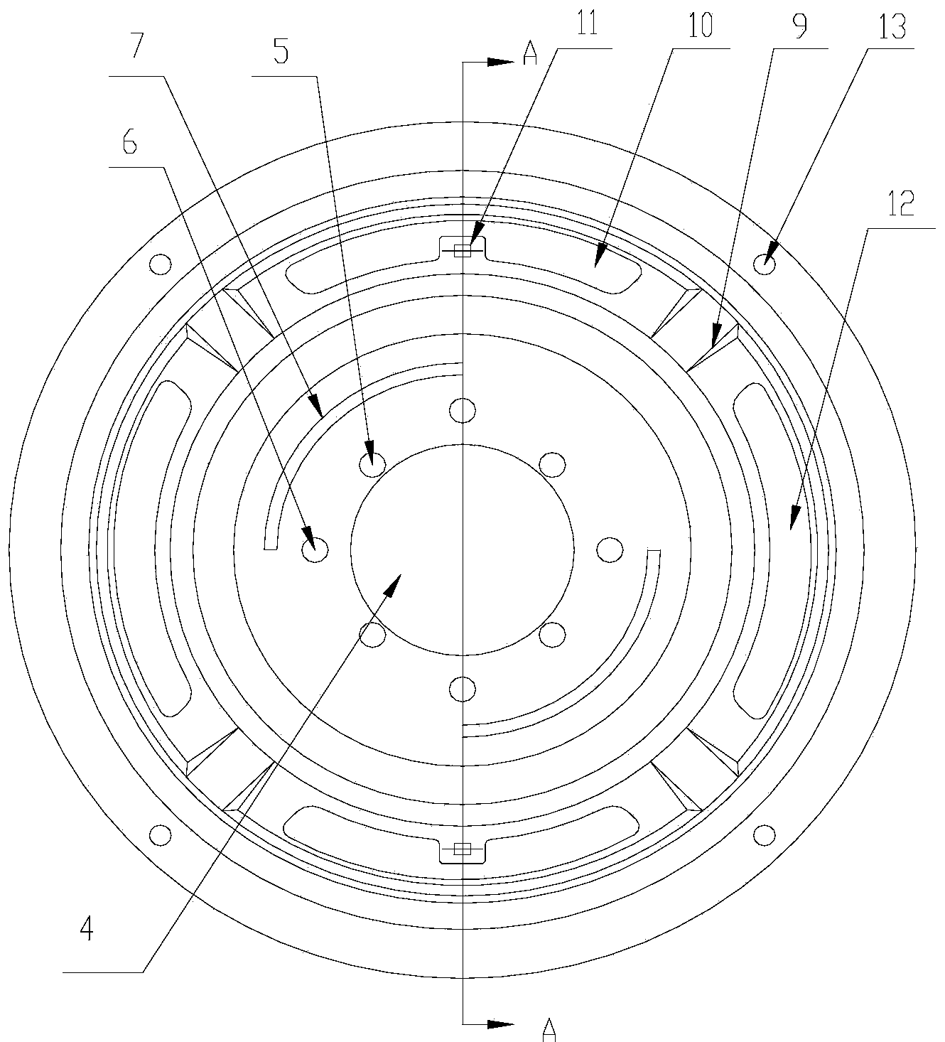
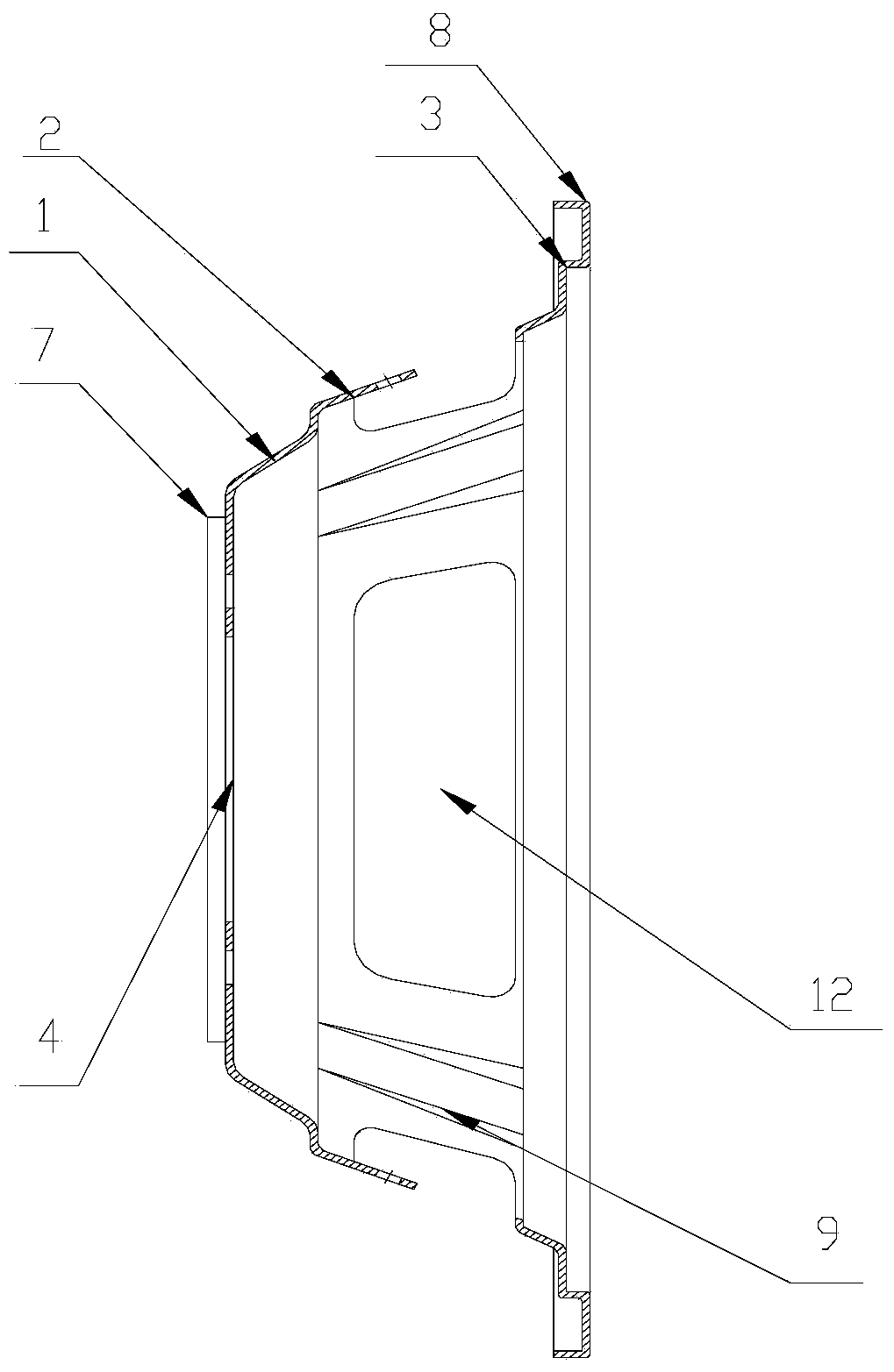
[0024] like figure 1 and figure 2 As shown, a processing technology of a loudspeaker pot frame with precisely stamped riveting holes and mounting holes includes the following steps:

[0025] Step 1: cut the material, cut out a coil material that is 230 millimeters wide on the cold-rolled carbon steel sheet by a shearing machine;

[0026] Step 2: Blanking, punching out a circular blank with a diameter of 227 mm on the raw material through a blanking die;

[0027] Step 3: punching a positioning hole, punching a positioning hole with a diameter of 16 mm in the center of the blank through a positioning hole die;

[0028] Step 4: Stretching. Stretching the billet punched with positioning holes through a stretching die into a bowl-shaped semi-finished product. The three steps are composed of steps from bottom to top, the first step 1 with a height of 9 to 9.4 mm, the second step 2 with a height of 31.1 to 31.4 mm, and the second step with a height of 4.3 to 4.7 mm. Three steps ...


PUM


Abstract

The invention discloses a processing technology of a speaker frame with precisely punched riveting holes and mounting holes. The processing technology comprises a series of steps of cutting, blanking, punching location holes, drawing, punching and trimming, punching the riveting holes, punching shock absorption slots, flanging and screeding, punching ear patterns, punching ear holes, punching single patterns, and punching the mounting holes. The invention aims to provide the processing technology of the speaker frame with the precisely punched riveting holes and mounting holes.

Description

technical field [0001] The invention relates to the manufacturing field of audio equipment, in particular to a processing technology of a loudspeaker basin frame with precisely punched riveting holes and mounting holes. Background technique [0002] The loudspeaker is a transducer device that converts electrical signals into acoustic signals, and the performance of the loudspeaker has a great influence on the sound quality. The loudspeaker is the weakest part in the audio equipment, but it is the most important part for the sound effect. There are many types of speakers, and their prices vary widely. Audio electric energy makes its paper cone or diaphragm vibrate and resonate (resonate) with the surrounding air through electromagnetic, piezoelectric or electrostatic effects to produce sound. [0003] The structure of the loudspeaker generally includes a bracket, a magnet, a pot frame, a fixed core support piece, a cone-shaped paper cone, etc. Among them, the pot frame is g...

Claims


Application Information

Patent Timeline
10 Sep 2014
Publication
CN104038883A
IPC
H04R31/00
Inventors
冯玉权