Image processing apparatus and image processing method

一种图像处理装置、对象图像的技术,应用在图像数据处理、图像增强、图像分析等方向,能够解决误选择应连接的边缘等问题

Inactive Publication Date: 2012-05-09
OLYMPUS CORP
View PDF4 Cites 18 Cited by
  • Summary
  • Abstract
  • Description
  • Claims
  • Application Information

AI Technical Summary

Problems solved by technology

Therefore, if there is a distance between the edges to be connected, or if the direction of the edges to be connected deviates, or if the edges to be connected and their connected parts are not smooth, there may be errors in selecting the edges to be connected possibility of

Method used


Image

  • Image processing apparatus and image processing method
  • Image processing apparatus and image processing method
  • Image processing apparatus and image processing method

Examples


Embodiment approach 1

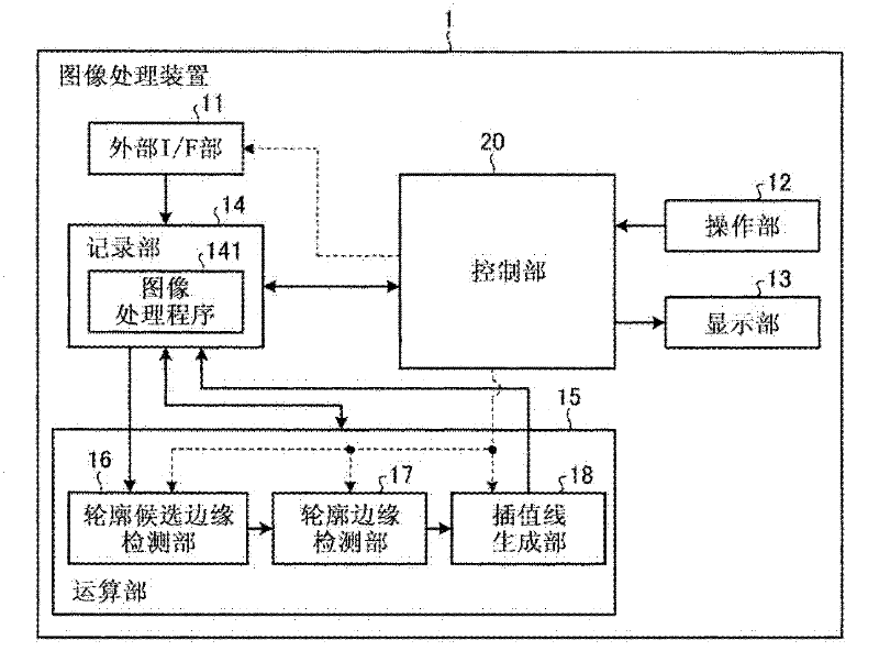
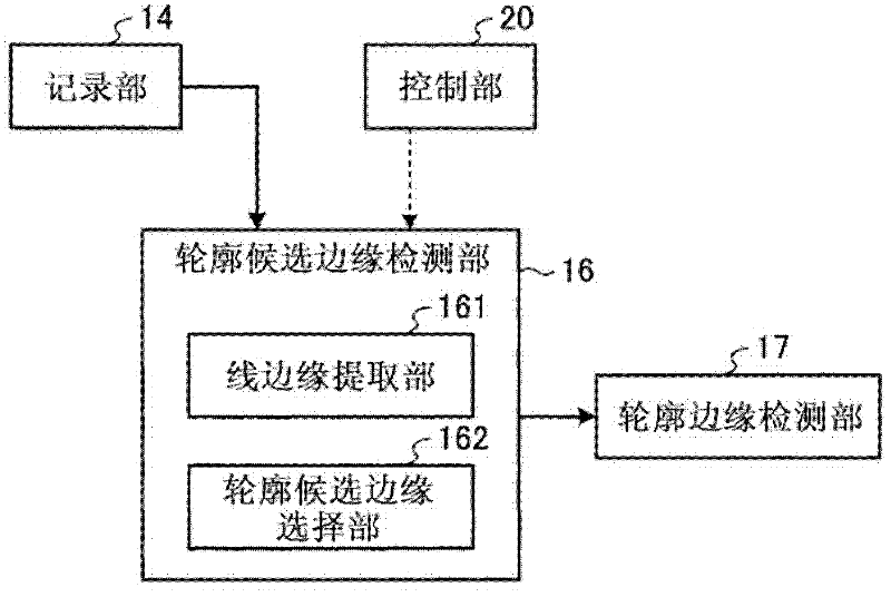
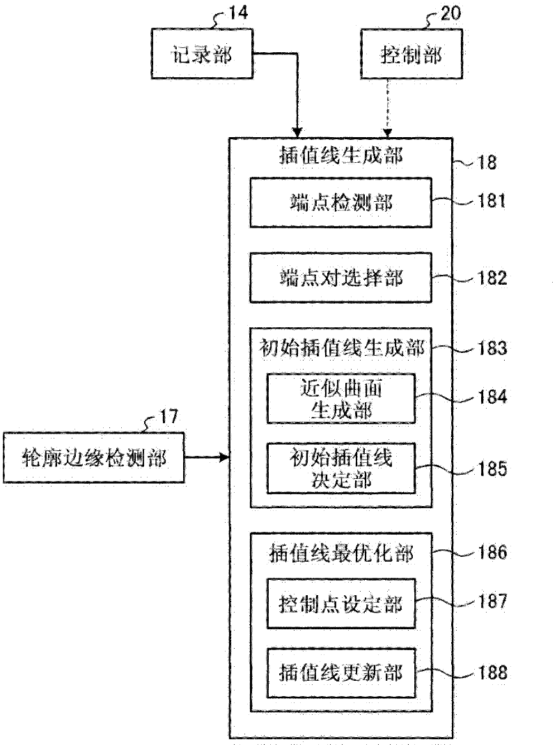
[0037] First, an image processing device according to Embodiment 1 will be described. figure 1 It is a block diagram illustrating an example of the functional configuration of the image processing device 1 according to the first embodiment. and, figure 2 It is a block diagram illustrating a configuration example of the contour candidate edge detection unit 16 according to Embodiment 1, image 3 It is a block diagram illustrating a configuration example of the interpolation line generation unit 18 according to the first embodiment. In addition, in Figure 1 ~ Figure 3 In , solid lines show data signal lines that connect various parts of the image processing device 1 to transmit data signals such as image signals, and dotted lines show control signal lines that transmit control signals.

[0038] Such as figure 1 As shown, the image processing device 1 according to Embodiment 1 has an external interface (I / F) unit 11, an operation unit 12, a display unit 13, a recording unit...

Deformed example 1

[0114] Figure 16 It is a block diagram illustrating a configuration example of the contour candidate edge detection unit 16 a in Modification 1 of Embodiment 1. The image processing device of Modification 1 can adopt the following Figure 16 The contour candidate edge detection section 16a shown is replaced by figure 1 The structure of the contour candidate edge detection unit 16 is realized. In addition, in Figure 16 In , the same reference numerals are assigned to the same structures as those in the first embodiment. Such as Figure 16 As shown, in Modification 1, the contour candidate edge detection unit 16 a includes a line edge extraction unit 161 , a branch edge removal unit 163 a, and a contour candidate edge selection unit 162 .

[0115] The branch edge removal unit 163 a removes a line edge portion branched from the line edge extracted by the line edge extraction unit 161 . Furthermore, in Modification 1, the contour candidate edge selection unit 162 selects a...

Deformed example 2

[0119] Figure 19 It is a block diagram illustrating a configuration example of the interpolation line generation unit 18 b in Modification 2 of Embodiment 1. The image processing device of Modification 2 can use Figure 19 Shown interpolation line generator 18b to replace figure 1 The interpolation line generation unit 18 is realized. In addition, in Figure 19 In , the same reference numerals are assigned to the same structures as those in the first embodiment. Such as Figure 19 As shown, in Modification 2, the interpolation line generation unit 18b includes: an end point detection unit 181, an end point pair selection unit 182, an initial interpolation line generation unit 183, and an interpolation line optimization unit 186b. Then, in Modification 2, the interpolation line optimization unit 186b has a route search unit 189b.

[0120] The difference between Modification 2 and Embodiment 1 is that Figure 6 In the interpolation line generation processing of , route s...


PUM


Abstract

An image processing apparatus includes a contour-candidate-edge detecting unit that detects, as contour candidate edges, edges on the basis of a gradient magnitude of each pixel in a target image; a contour-edge detecting unit that detect contour edges by performing thresholding on gradient magnitudes of the contour candidate edges; an interpolation-line generating unit that generates a plurality of interpolation lines for connecting end points of respective end-point pairs on the basis of gradients of pixel values between the end points of the respective end-point pairs while each of the end point pairs is made up of an end point of an identical contour edge as a connection base and an end point of a different contour edge as a connection destination; and a contour-edge interpolating unit that selects one of the interpolation lines on the basis of gradients of pixel values of pixels on the interpolation lines, and interpolates a contour edge between end points, which are to be connected with the selected interpolation line, with the selected interpolation line.

Description

technical field [0001] The present invention relates to an image processing device and an image processing method for detecting contour edges from an object image. Background technique [0002] In general, edge detection within an image is performed by detecting the position where the gradient changes the most (the position where the gradient is steep and the value of the gradient strength is large compared to the surrounding area), basically, by calculating the gradient from the brightness value of the image Gradient strength, thresholding is performed on the gradient strength for detection. When such an edge detection method is used to detect a contour edge from an image, there are cases where the contour edge is blurred due to factors such as the accuracy of the edge detection algorithm, noise, blurring (blurring) of the image, or a subjective contour portion. An interruption occurred. As a method for connecting such interrupted and discrete contour edges, conventionall...

Claims


Application Information

Patent Timeline
Patent Type & Authority Applications(China)
IPC IPC(8): G06T5/00
CPCG06T2207/30092G06T7/0079H04N5/142G06T2207/10068G06T7/0085G06T2207/30028G06T2207/20136G06T7/13G06T7/181
Inventor 河野隆志神田大和北村诚松田岳博弘田昌士
Owner OLYMPUS CORP
Why Eureka
Try Eureka