Contact switch structure
A contact switch and switch technology, applied in the direction of contact engagement, etc., can solve the problems of difficult to design high-voltage, small-volume contact switch products, etc., and meet the requirements of reducing the reset elasticity, shrinking the volume, and high isolation voltage Effect
- Summary
- Abstract
- Description
- Claims
- Application Information
AI Technical Summary
Problems solved by technology
Method used
Image

Examples
Embodiment 1
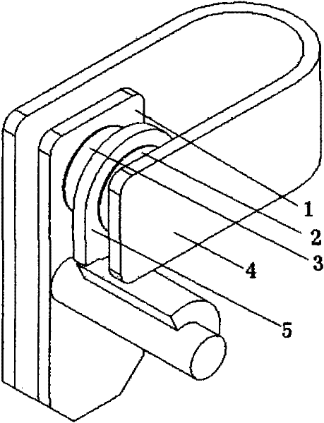
[0014] figure 1 The described SPST contact switch structure includes: a static contact terminal 1, a moving contact 2, a static contact 3, a moving contact terminal 4, and an insulating partition 5. The insulating partition is integrated with a rotating shaft. When the switch performs on-off and off-function switching, the mechanical force pulls the contact end of the movable contact terminal, and at the same time transmits the force to the rotating shaft. Driven by the rotating shaft, the insulating partition acts as a bob up and down. When the switch is in the closed state, the insulating partition swings to the bottom of the contacts, and when the switch is in the open state, the insulating partition is inserted between the moving and static contacts.
Embodiment 2
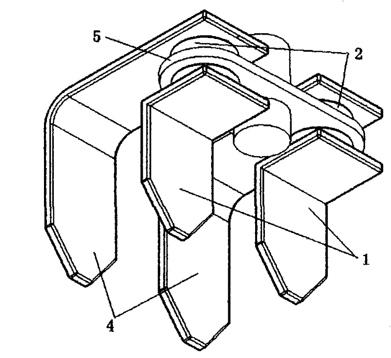
[0016] figure 2 Described is a TPST contact switch structure including: static contact terminal 1, moving contact 2, static contact 3, moving contact terminal 4, and insulating partition 5. Two insulating partitions are connected symmetrically with a rotating shaft. The rotating shaft is set between the two sets of contact terminals. Driven to the rotating shaft, the insulating partition is driven by the rotating shaft to make a 90-degree step-by-step rotation. When the switch is in the closed state, the insulating partition is turned to the neutral position between the two groups of contact terminals. When the switch is in the off state, the insulating partition is inserted between the corresponding moving and static contacts.
Embodiment 3
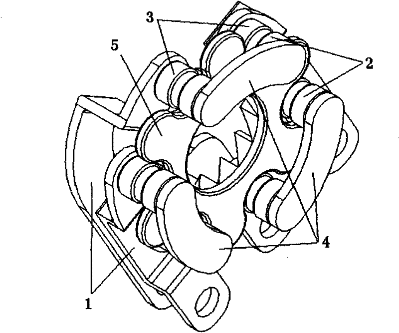
[0018] image 3 The described three pole single throw contact switch structure includes: static contact terminal 1 , moving contact 2 , static contact 3 , moving contact terminal 4 , and insulating partition 5 . Six insulating partitions are integrated with a hollow rotating shaft, and one end of the hollow rotating shaft is provided with helical teeth for direct motion and variable rotation. When the switch performs the function of switching on and off, the mechanical force pulls the contact end of the moving contact terminal, and at the same time Through the transmission of force to the rotating shaft, the insulating partition is driven by the rotating shaft to make a stepwise rotation of 30 degrees. When the switch is in the closed state, the insulating partition is turned to the neutral position between the two groups of contact terminals. When the switch is in the off state, the insulating partition is inserted between the corresponding moving and static contacts.
[001...
PUM
 Abstract
Description
Claims
Application Information
 - R&D Engineer
- R&D Manager
- IP Professional
- Industry Leading Data Capabilities
- Powerful AI technology
- Patent DNA Extraction
Browse by: Latest US Patents, China's latest patents, Technical Efficacy Thesaurus, Application Domain, Technology Topic.
© 2024 PatSnap. All rights reserved.Legal|Privacy policy|Modern Slavery Act Transparency Statement|Sitemap