protective device
A protection device and mounting part technology, which is applied to emergency protection circuit devices, coupling devices, circuit devices, etc., can solve the problem of not being able to hold the SPD plug firmly, and achieve the effects of miniaturization, lightening of burden, and light contact.
- Summary
- Abstract
- Description
- Claims
- Application Information
AI Technical Summary
Problems solved by technology
Method used
Image
Examples
no. 1 example
[0065] (Structure of the first embodiment)
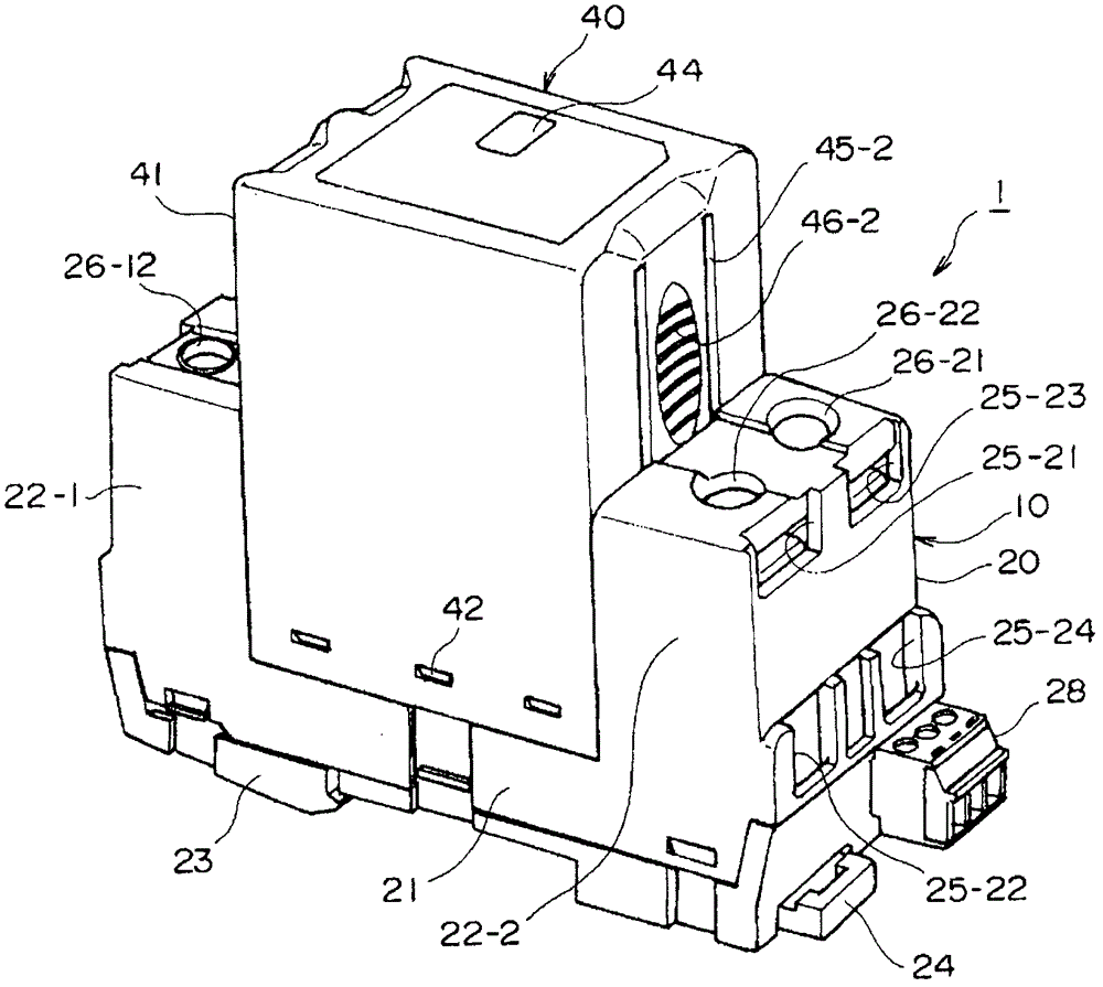
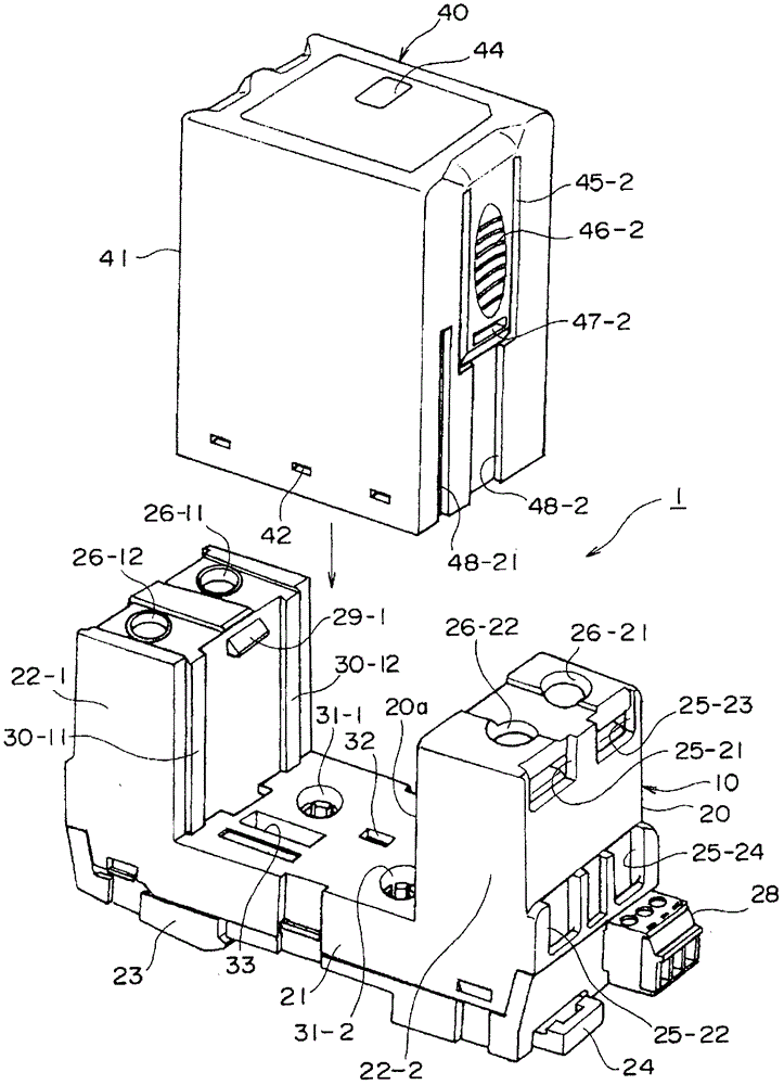
[0066] figure 1 It is a perspective view showing the overall appearance of the protective device according to the first embodiment of the present invention. figure 2 yes means figure 1 A perspective view of the separated state of the socket board 10 and the SPD plug 40 in the protection device 1 of FIG.
[0067] The protection device 1 is a power supply protection device for protecting power supply equipment by suppressing abnormal voltages and currents such as lightning and surges intruding into a circuit (such as a power line), and has a socket board 10 and a plug (such as an SPD plug) 40. The protection device 1 is configured such that the SPD plug 40 is along figure 2 The direction shown by the arrow in the socket can be inserted or detachably inserted and installed on the socket board 10 .
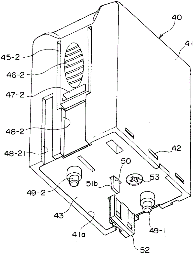
[0068] image 3 is seen from the bottom figure 2 A perspective view of the SPD plug 40. Figure 4A ~ Figure 4E yes figure 1 Fiv...
no. 2 example
[0128] Figure 10A It is a perspective view showing the plug terminal on the SPD plug side and the socket contact on the socket board side in the second embodiment of the present invention. Figure 10B yes means Figure 10A Cross-sectional view of the engaged state of the plug terminal and the socket contact.
[0129] The socket contact 134 on the socket board side in the second embodiment corresponds to the socket contact 34-1 of the first embodiment, and consists of an elastic cylindrical portion 134a and a plurality of cut grooves formed in the cylindrical portion 134a. 134c and a first mounting portion (for example, a first screw portion) 134d, and is formed of a metal member.
[0130] The cylindrical portion 134a is a member that is open at one end and closed at the other end, and the cylindrical portion 134a has an opening from figure 2 The illustrated insertion holes 31-1, 31-2 on the side of the socket housing 20 are installed in the respective insertion holes 31-1...
no. 3 example
[0136] Figure 11A It is a perspective view showing the plug terminal on the SPD plug side and the socket contact on the socket board side in the third embodiment of the present invention. Figure 11B yes means Figure 11A Cross-sectional view of the engaged state of the plug terminal and the socket contact.
[0137] in the Figure 11A with Figure 11B , for the same as shown in the second embodiment Figure 10A with Figure 10B The same reference numerals are assigned to the same elements in the elements.
[0138] In the third embodiment, there are receptacle contacts 134A having a shape different from that of receptacle contact 134 on the receptacle board side in the second embodiment and plug terminals 149 on the plug terminal side as in the second embodiment. In the receptacle contact 134A of the third embodiment, instead of the cylindrical portion 134a of the second embodiment, there are two cylindrical portions 134a-1, 134a-2, and the two cylindrical portions 134a-...
PUM
 Abstract
Description
Claims
Application Information
 - R&D
- Intellectual Property
- Life Sciences
- Materials
- Tech Scout
- Unparalleled Data Quality
- Higher Quality Content
- 60% Fewer Hallucinations
Browse by: Latest US Patents, China's latest patents, Technical Efficacy Thesaurus, Application Domain, Technology Topic, Popular Technical Reports.
© 2025 PatSnap. All rights reserved.Legal|Privacy policy|Modern Slavery Act Transparency Statement|Sitemap|About US| Contact US: help@patsnap.com


