Synthetic method of stereoscopic elements in combined stereoscopic image system collected by sparse lens

A stereoscopic image and in-image technology, which is applied in the field of virtual synthesis of stereoscopic meta-images in a combined stereoscopic image system, can solve the problems of inability to realize virtual viewpoint synthesis and no virtual synthesis technology.

Inactive Publication Date: 2013-09-04
JILIN UNIV
View PDF5 Cites 4 Cited by
  • Summary
  • Abstract
  • Description
  • Claims
  • Application Information

AI Technical Summary

Problems solved by technology

ImageWarping uses the reference image containing depth information to draw the target image under the new viewpoint. It is essentially a spatial reprojection technology. Because the DIBR technology draws the virtual viewpoint quickly and has high image quality, it is very suitable for the virtualization of stereoscopic images. Viewpoint generation, but DIBR technology cannot realize the synthesis of a large number of virtual viewpoints, and for the local imaging characteristics of the camera matrix of the combined stereoscopic image system, there is currently no ready-to-use virtual synthesis technology

Method used


Image

  • Synthetic method of stereoscopic elements in combined stereoscopic image system collected by sparse lens
  • Synthetic method of stereoscopic elements in combined stereoscopic image system collected by sparse lens
  • Synthetic method of stereoscopic elements in combined stereoscopic image system collected by sparse lens

Examples


Embodiment Construction

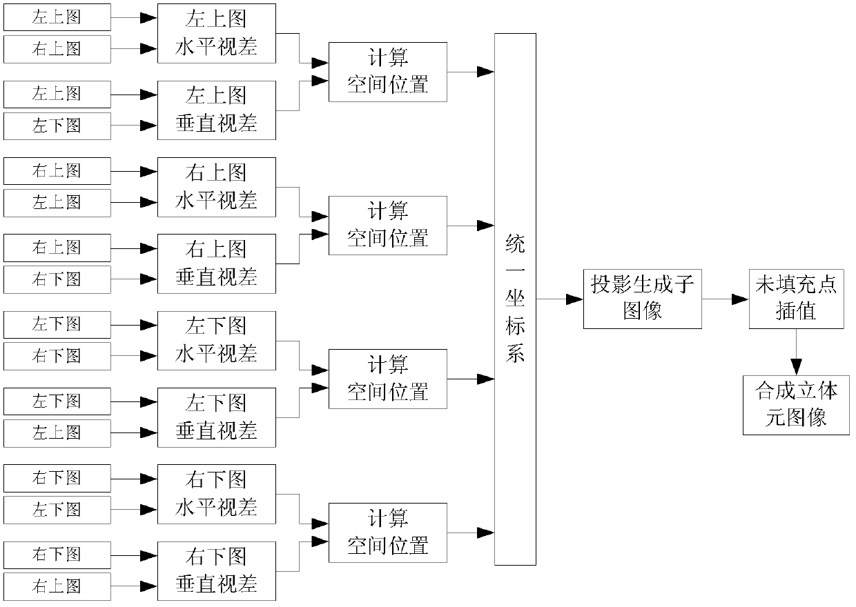
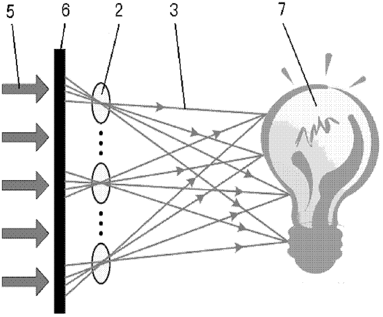
[0055] The present invention will be further described in detail below in conjunction with the accompanying drawings. Here, will Figure 5 The image collected by the 2×2 sparse camera matrix acquisition platform shown in is used as the original image of the synthetic stereo element image, such as Image 6 Shown is the original image collected by the 2×2 sparse camera matrix, the specific process (such as figure 1 shown) includes the following steps:

[0056] 1. Set the sparse camera matrix (such as Figure 5 shown), it must be ensured that all the cameras in the matrix are in the same plane, the lines of cameras in each row are parallel to each other, the lines of cameras in each column are also parallel to each other, and the lines of cameras in each row and column of cameras are perpendicular to each other.

[0057] 2. Calculate the disparity map between each captured image and its horizontally adjacent images and the disparity map between vertically adjacent images resp...


PUM


Abstract

The invention discloses a synthetic method of stereoscopic elements in a combined stereoscopic image system collected by a sparse lens, and belongs to the technical field for generating stereoscopic images. The method comprises the following steps of: arranging a sparse camera matrix; calculating optical parallax image between each shot image and an adjacent horizontal image and between each shot image and an adjacent vertical image; expanding a binocular stereoscopic vision model into a multi-eye stereoscopic vision model, and calculating spatial location coordinates of actual object points corresponding to the pixel points in each image according to a horizontal parallax image and a vertical parallax image of each image; transforming the spatial location coordinates of the actual object points corresponding to the pixel points calculated in all images into the same coordinate system; virtually simulating a camera array, projecting the actual object points corresponding to the pixel points in each image under the same coordinate system to each virtual camera to generate sub-images; interpolating the points without being filled; and generating a stereoscopic element image. The synthetic method can be used for accomplishing the parallel generation of a great quantity of virtual view points and is more suitable for virtual synthetics of the stereoscopic element image; and therefore, for an image source of the combined stereoscopic image system, live action shooting can be carried out in place of computer production.

Description

technical field [0001] The invention belongs to the technical field of stereoscopic image generation, and in particular relates to a virtual synthesis method of stereoscopic element images in a combined stereoscopic image system. Background technique [0002] For a long time, the acquisition of visual information of the displayed world mainly comes from single-camera capture, and this acquisition form cannot bring the human eye a sense of depth, three-dimensionality, and all-round understanding of objects. Driven by the development of related disciplines and new demands for new technologies, stereoscopic display technology has emerged as the times require. Stereoscopic display technology mainly includes stereoscopic display technology utilizing binocular parallax and true stereoscopic display technology. At present, stereoscopic display technology with binocular parallax is widely used in movie theaters. This technology is easy to implement and low in cost. However, because...

Claims


Application Information

Patent Timeline
Patent Type & Authority Patents(China)
IPC IPC(8): H04N13/00
Inventor 王世刚吕源治金福寿赵岩陈贺新王学军祝宇鸿桑爱军
Owner JILIN UNIV
Why Eureka
Try Eureka