Fan impeller

A fan impeller and wheel hub technology, which is applied in the field of industrial ventilation, can solve problems such as easy changes in positional relationship, difficulty in meeting use requirements, deformation, etc., and achieve the effect of enhancing strength and taking into account strength and ventilation performance

Inactive Publication Date: 2012-05-16
TIANJIN CHANGGUANG WEIYE SPECIAL FAN
View PDF0 Cites 3 Cited by
  • Summary
  • Abstract
  • Description
  • Claims
  • Application Information

AI Technical Summary

Problems solved by technology

The impeller usually rotates at about 1480rpm. In industrial furnaces such as all-hydrogen bell furnaces, there is a hydrogen atmosphere. In order to make the gas in the furnace circulate faster and achieve sufficient heat exchange, it is necessary to increase the impeller revolution to 2100-2200rpm. In this case The structural strength of the existing impeller is difficult to meet the requirements of use, and it will cause deformation when used under high temperature conditions, especially the rear disc and the positional relationship between the front disc and the rear disc are easy to change, affecting the normal use of the fan impeller

Method used


Image

  • Fan impeller
  • Fan impeller
  • Fan impeller

Examples


Embodiment Construction

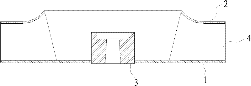
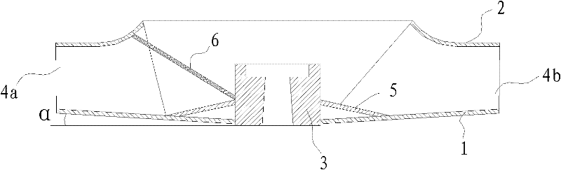
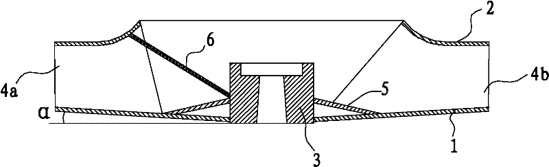
[0013] see figure 2 The fan impeller of the present invention includes a hub 3, the hub 3 has an axial through hole for penetrating the drive shaft, the bottom periphery of the hub 3 is provided with an annular rear disc 1, the bottom edge of the blade is fixed on the upper surface of the rear disc 1, and the top of the blade All along the bottom surface that is fixed on the ring-shaped front plate 2.

[0014] The descriptions about orientation in the present invention, such as up, down, top, and bottom, are relative to the drawings, and do not represent absolute orientations.

[0015] Between the outer wall of the hub 3 and the upper surface of the rear disc 1, a cone-shaped reinforcing cone 5 is arranged, the inner edge of the middle hole of the reinforcing cone 5 is connected with the outer wall of the hub 3, and the bottom edge of the reinforcing cone 5 is connected with the upper surface of the rear disc 1 .

[0016] The annular rear disc 1 has a middle hole, and the i...


PUM


Abstract

The invention discloses a fan impeller, which comprises a hub, an annular rear disk connected to the periphery of the bottom part of the hub, a plurality of blades with the bottom edges fixed on the upper surface of the rear disk, and an annular front disk connected with the top edges of the blades, wherein a cone-ring-shaped conical stiffener is arranged between the outer wall of the hub and the upper surface of the rear disk, the blades are divided into short extended blades and long extended blades according to extended distance from the bottom edges of the blades to the hub, and the same number of short extended blades are arranged between any two adjacent long extended blades. The fan impeller has the beneficial effects that: the cone-ring-shaped conical stiffener is arranged between the outer wall of the hub and the upper surface of the rear disk, so that the strength of the rear disk is further enhanced, and the high-speed rotation of the fan impeller is ensured at high temperature without deformation. In addition, the blades with different lengths are adopted on the radial direction of the rear disk, so that both the strength and the ventilation performance of the fan impeller are taken into consideration.

Description

technical field [0001] The invention relates to the technical field of industrial ventilation, in particular to a fan impeller for driving gas circulation in an industrial furnace. Background technique [0002] see figure 1 The structure of the fan impeller in the prior art includes a hub 3, an annular rear disc 1 at the periphery of the hub 3, a blade 4 whose bottom edge is fixed on the surface of the rear disc 1, and an annular front disc 2 connected to the top edge of the blade 4. The hub 3 is a cylinder or cone with an axial through hole, and the through hole is used to penetrate the drive shaft. Generally, if the side of the blade near the hub extends until it is connected with the outer wall of the hub, it is called a long blade, otherwise the blade The side adjacent to the hub is not connected to the outer wall of the hub, and is called a short blade. [0003] The temperature in the industrial furnace used for heat treatment is high, which has high requirements for ...

Claims


Application Information

Patent Timeline
Patent Type & Authority Applications(China)
IPC IPC(8): F04D29/28
Inventor 刘金廷
Owner TIANJIN CHANGGUANG WEIYE SPECIAL FAN
Why Eureka
Try Eureka