Two-stage pressure revolution cushion valve

A rotary buffer and pressure valve technology, applied in fluid pressure actuators, servo motor components, mechanical equipment, etc., can solve the problems of rising manufacturing costs, inconvenient installation and use, and occupying a large space, so as to achieve easy production and assembly and The effect of installation and use, reasonable structure design, and convenient maintenance and adjustment

Inactive Publication Date: 2012-05-16
印辉
View PDF4 Cites 5 Cited by
  • Summary
  • Abstract
  • Description
  • Claims
  • Application Information

AI Technical Summary

Problems solved by technology

The single use of mechanical brake or the use of mechanical brake combined with a rotary buffer valve with only single-stage pressure regulation cannot meet the requirements of these three working conditions at the same time
In order to realize the above-mentioned control process, standard single-function hydraulic components are still mostly used and connected with complex piping. Therefore, it usually has a relatively large structure and is not concise and compact enough. There is one hydraulic component in the east and one hydraulic component in the west. The pipelines connecting them are also relatively complicated, easy to leak oil, and inconvenient to install and use. The volume is relatively large and takes up a large space, so the failure rate is high, there are many safety hazards, and the service life is not long
[0003] Although the Japanese patent application of JP2001302183A also discloses an oil pressure speed control device on a hoist or a crane, it still adopts standard single-function hydraulic components connected with complex piping to realize, so it certainly has the above-mentioned The structure is relatively large, not concise and compact enough, and the design of the detection mechanism and the gate device mechanism is relatively complicated, resulting in a substantial increase in manufacturing costs

Method used


Image

  • Two-stage pressure revolution cushion valve
  • Two-stage pressure revolution cushion valve
  • Two-stage pressure revolution cushion valve

Examples


Embodiment Construction

[0015] The following examples are used to illustrate the present invention, but are not intended to limit the scope of the present invention. All equivalent technical solutions also belong to the scope of the present invention, and the patent protection scope of the present invention should be limited by the claims.

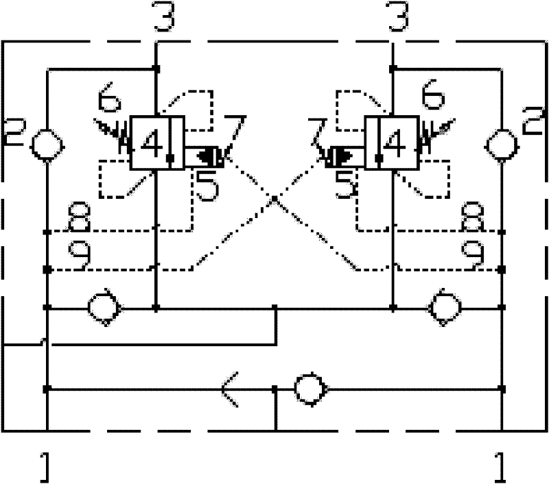
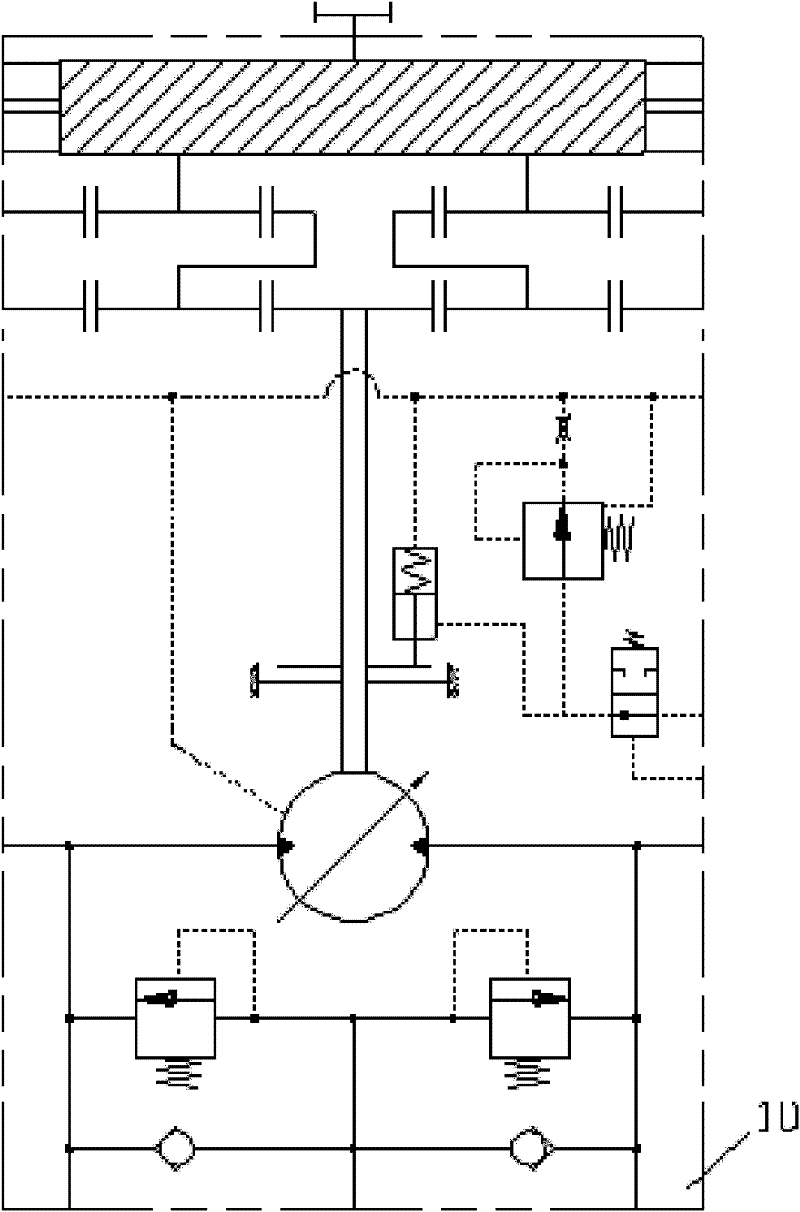
[0016] from figure 1 and figure 2 It can be seen that a two-stage pressure rotary buffer valve is composed of a pair of symmetrical two-way balance valves, an oil inlet pipe 1, a one-way valve 2 and an oil outlet pipe 3. It is characterized in that: the pair of oil inlet pipes The pipeline 1 is connected with the oil outlet pipeline 3 through a pair of one-way valves 2. The pressure spool 4 of the two-way balance valve is respectively provided with a pilot piston 5, a spring A6 and a spring B7. The pilot piston 5 passes through the oil The channel A8 and the oil channel B9 are respectively communicated with the two oil inlet pipelines 1 , and the pressure valve...


PUM


Abstract

The invention discloses a two-stage pressure revolution cushion valve which is used on a revolution system for a rotary drilling rig. The two-stage pressure revolution cushion valve consists of a pair of two-way balance valves with symmetrical structures; a pair of oil inlet pipelines are connected with oil outlet pipelines through a pair of check vales; pressure valve plugs of the balance valves are provided with pilot pistons, springs A, and springs B respectively; the pilot pistons are communicated with two oil inlet pipelines through oil pipelines respectively; and the pressure valve plugs are provided with pipelines which are connected with the oil outlet pipelines. The cushion valve has the multi-functional characteristics, integrates a large number of functions which are required by the revolution working conditions, and can realize the high-pressure starting and low-pressure braking functions during use, and solve the problems of low revolution stability and revolution drifting in the revolution process and the working drilling process of the rotary drilling rig. Meanwhile, the cushion valve has a compact structure, pipeless design, and a small volume, is easy to produce, assemble and use, and hardly leaks oil.

Description

technical field [0001] The invention relates to a rotary buffer valve used in construction machinery with a large-load working device and can be rotated 360 degrees, in particular to a rotary buffer valve used in the rotary system of a rotary drilling rig. Background technique [0002] Taking the rotary drilling rig as an example, for the rotary system of the rotary drilling rig, it is required to provide sufficient starting torque when starting, smooth buffer control when stopping, and rotary braking when the drilling rig is drilling. The use of mechanical brakes alone or the use of mechanical brakes in conjunction with a rotary buffer valve with only single-stage pressure regulation cannot take into account the requirements of these three working conditions at the same time. In order to realize the above-mentioned control process, standard single-function hydraulic components are still mostly used, which are connected by complicated pipes, so the structure is usually relat...

Claims


Application Information

Patent Timeline
Patent Type & Authority Applications(China)
IPC IPC(8): F15B13/02
Inventor 邱国东郝永辉李广伟
Owner 印辉
Why Eureka
Try Eureka