Cracking-prevention structure suited on lens

A technology for optical mirrors and flanges, which is applied in the field of anti-cracking structure of optical mirror sleeves. It can solve the problems of easy cracking, increased product cost, and water leakage, so as to improve air tightness, increase contact area, and prevent cracking. Effect

Inactive Publication Date: 2012-05-16
JIANGSU CHANGCHENG AUTOMOBILE PARTS
0 Cites 0 Cited by

AI-Extracted Technical Summary

Problems solved by technology

[0002] The current structure of the light distribution mirror is mainly composed of two entities bonded to each other on one side. During the production and use of the lamp, due to the influence of various objective conditions on the lamp, it is easy to crack at the joint of the two entities, result...

Abstract

The invention relates to a cracking-prevention structure suited on a lens, which consists of the lens (1) and an injection-molding lens (2), wherein the lens (1) is provided with a flange (3), the injection-molding lens (2) is provided with a rove, the flange (3) of the lens (1) is clamped into the groove of the injection-molding lens (2); the cracking-prevention structure is characterized in that: the flange (3) of the lens (1) is a reinforcing rib. In the invention, the contact area of the two lenses can be directly increased, the stressed force in a unit area is reduced, the air tightness of a lamp is effectively improved, the cracking is prevented, and the yield of the products is improved to 93.7% from 75.2 percent.

Application Domain

Road vehiclesLight fastenings

Technology Topic

OptoelectronicsFlange +1

Image

  • Cracking-prevention structure suited on lens
  • Cracking-prevention structure suited on lens

Examples

  • Experimental program(1)

Example Embodiment

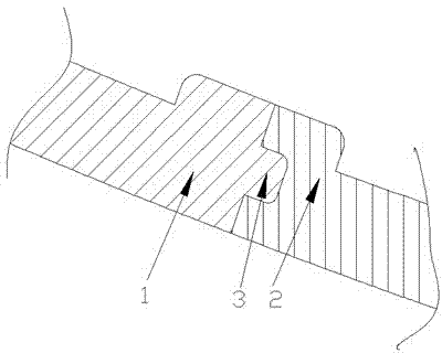
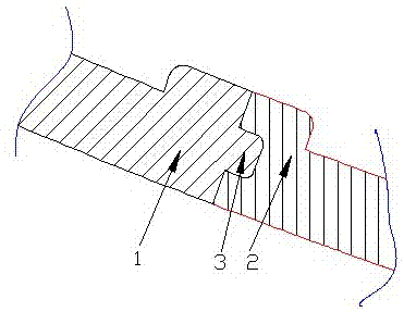
[0007] Depend on figure 1 It is well known that the light distribution mirror cover of this embodiment has a structure to prevent cracking, and the mold of the injection molding machine is molded and injected, and the light distribution mirror 1 and the injection molded light distribution mirror 2 will be integrated with each other. A flange structure 3 is added around the mirror. The size of the rib is 1 mm×1mm. The injection molded light distribution mirror 2 has a groove, and the light distribution mirror flange 3 is inserted into the groove of the injection molded light distribution mirror 2. During production and use During the process, the lamps and lanterns will be affected by forces from various aspects. The structure light distribution mirror of the present invention is red 2, and the injection molding light distribution mirror 2 is white. This structure reduces product cracking, improves product quality and qualified rate, and reduces cost.

PUM

no PUM

Description & Claims & Application Information

We can also present the details of the Description, Claims and Application information to help users get a comprehensive understanding of the technical details of the patent, such as background art, summary of invention, brief description of drawings, description of embodiments, and other original content. On the other hand, users can also determine the specific scope of protection of the technology through the list of claims; as well as understand the changes in the life cycle of the technology with the presentation of the patent timeline. Login to view more.

Similar technology patents

Safe portable multifunctional oxygen-hydrogen integrated machine

ActiveCN105063652Aincrease contact areaIncreased solubility
Owner:保定市氢水源生物科技有限公司

Touch panel

ActiveUS20140184936A1reduce visibilityincrease contact area
Owner:SAMSUNG ELECTRO MECHANICS CO LTD

Classification and recommendation of technical efficacy words

  • Improve air tightness
  • increase contact area

Electronic component

InactiveCN101599468AImprove air tightness
Owner:TAIYO YUDEN KK

Anti-abrasion high-lubrication additive composite of lubricating oil or engine oil

InactiveCN102676271AReduce surface friction coefficientImprove air tightness
Owner:黄朝扬

Compressor pump coupling method

InactiveCN1952401AImprove air tightnessEliminate lubricant leakage
Owner:LG ELECTRONICS (TIANJIN) APPLIANCES CO LTD

Blood vessel interventional operation conduit or guide wire control device based on two-point clamping

ActiveCN103157170Aincrease contact areaIncrease the upper limit of friction
Owner:北京中科鸿泰医疗科技有限公司

Continuous feeding device for electric arc furnace preheated by flue gases

InactiveCN103075881AImprove mechanical efficiencyincrease contact area
Owner:CISDI ENG CO LTD
Why Eureka
Try Eureka