Bridging structure for conductor terminals

A technology of wire terminal and bridge structure, which is applied in the field of wire terminal devices and can solve problems such as poor heat dissipation and unsatisfactory conductivity

Active Publication Date: 2012-05-16
SWITCHLAB SHANGHAI
View PDF5 Cites 6 Cited by
  • Summary
  • Abstract
  • Description
  • Claims
  • Application Information

AI Technical Summary

Problems solved by technology

[0009] The technical problem to be solved by the present invention is to provide a bridging structure for wire terminals, change the structure of the bridge, and its combination form with terminals, spring sheets, and conductors, and solve the problem under the condition of satisfying stability and safety. Unsatisfactory electrical conductivity, poor heat dissipation and obvious temperature rise

Method used


Image

  • Bridging structure for conductor terminals
  • Bridging structure for conductor terminals
  • Bridging structure for conductor terminals

Examples


Embodiment Construction

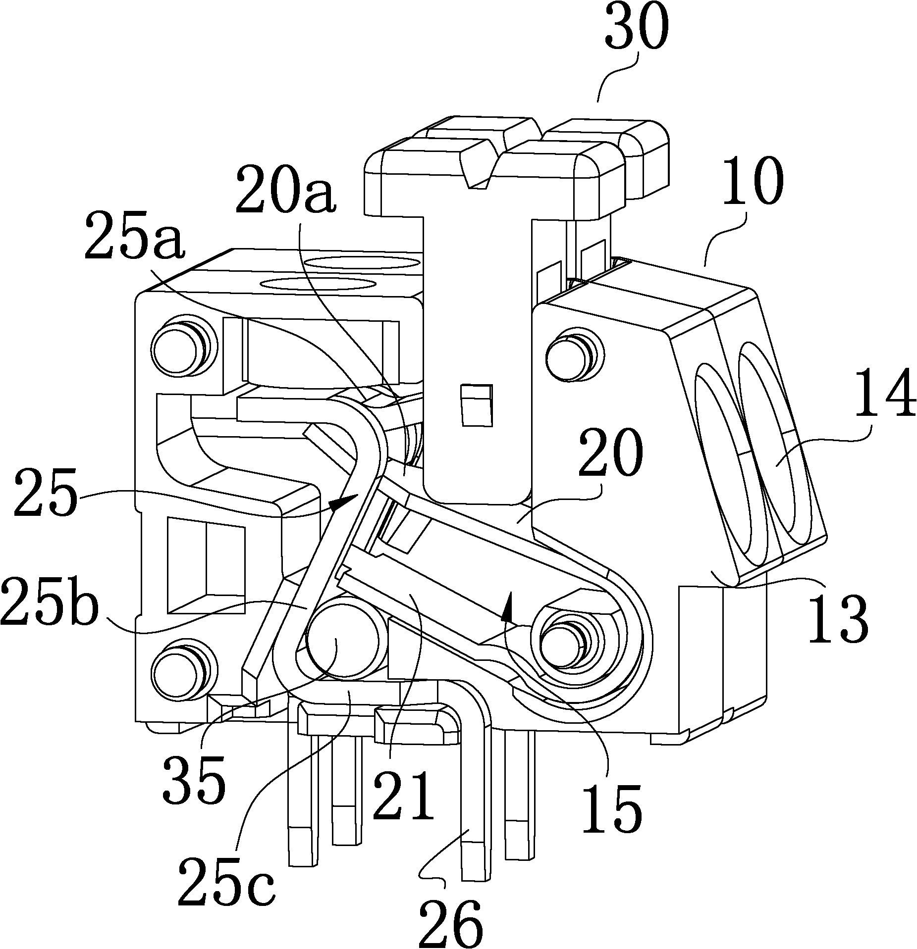
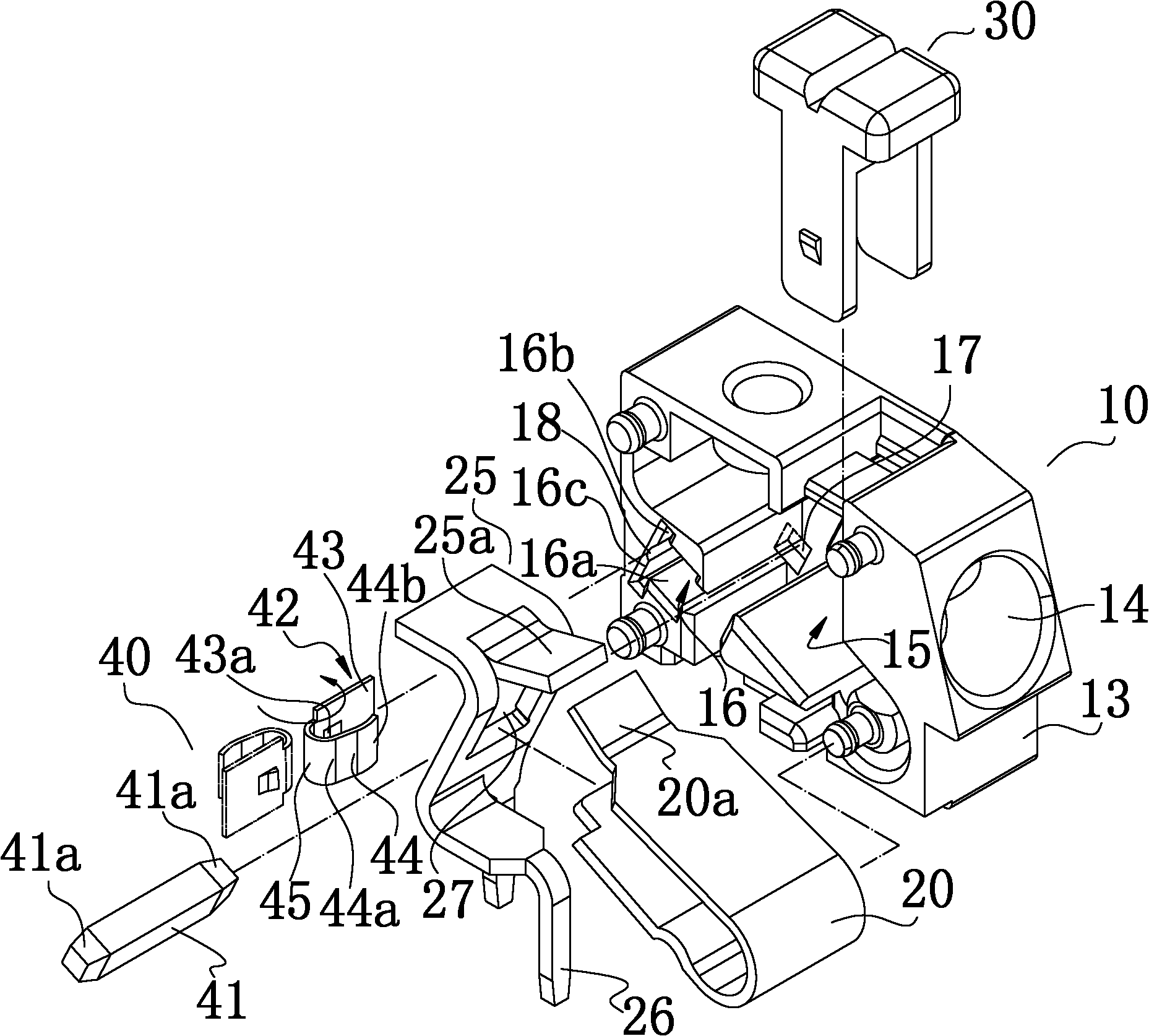
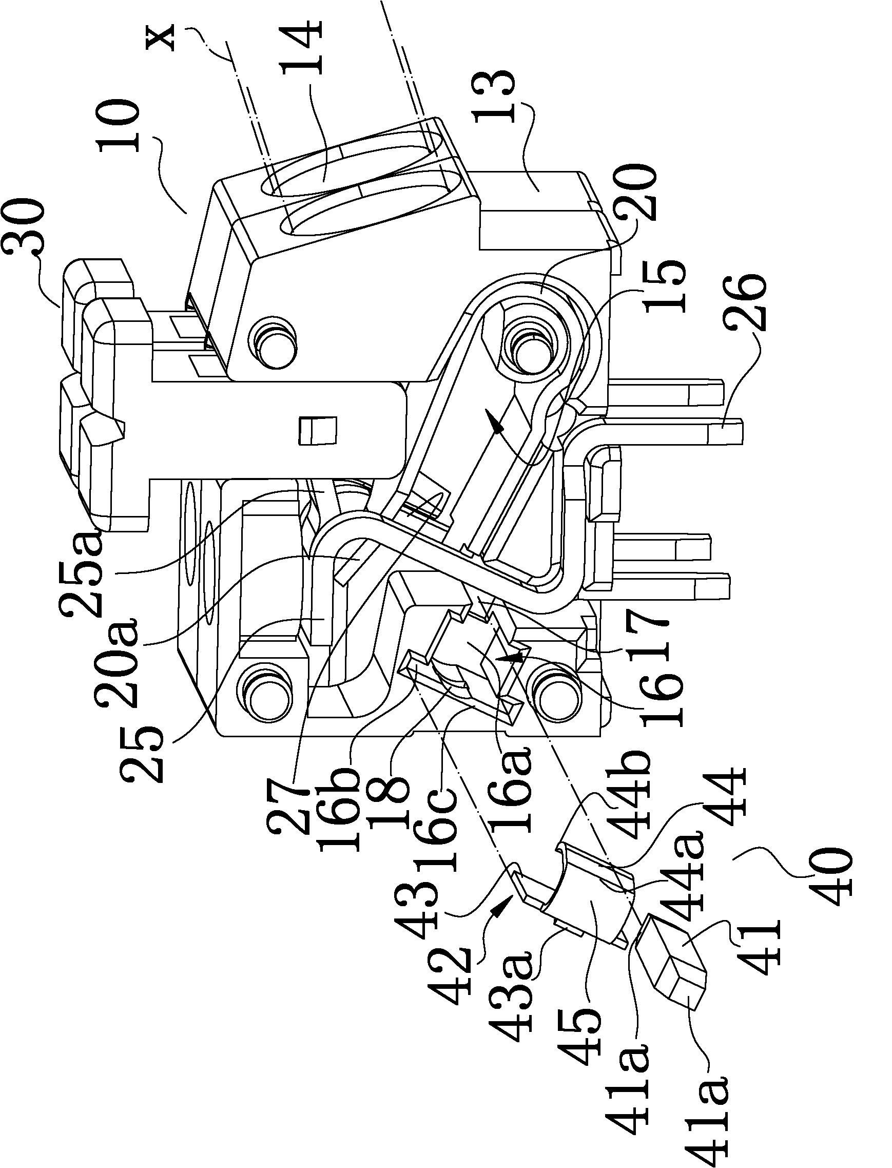
[0037] see figure 2 , image 3 and Figure 4 , the present invention is used for the bridging structure of the wire terminal, which is a combination of a wire (or connection) terminal 10 and a network bridge 40 . The network bridge 40 can be elastically inserted into the connection terminals 10 to electrically connect at least two connection terminals 10 to each other. image 3 , Figure 4 In particular, two terminals 10 arranged together are depicted, and the terminal 10 is chosen to be in the form of an insulating housing 13 made of plastic material. The housing 13 has a plurality of inlets 14 for the wires x received from the machine equipment to be inserted into the housing 13 . The terminal 10 or the housing 13 defines a cavity 15 , the spring piece 20 and the conductor (or metal piece) 25 are fitted in the cavity 15 , and form contact or electrical connection with the wire x inserted into the housing 13 .

[0038] In this embodiment, the spring sheet 20 and the con...


PUM


Abstract

The present invention discloses a bridging structure for conductor terminals, which is combination of the conductor terminals and a bridge. The bridge comprises a contactor and an elastic part. The elastic part is provided with the following components: a first edge, a second edge, and a bent edge which is connected with the first edge and the second edge. The contactor is a cylindrical structure of which the cross section is similar to a polygon. The contactor is in surface contact with the conductors which are configured in the conductor terminals. A groove chamber and a through hole are limited on each terminal for accommodating the bridge. Furthermore a second edge of the elastic part always presses the contactor to the conductors which are configured in the terminals so at least two terminals are electrically connected mutually. The bridging structure settles the following problems of the bridge: lower heat radiation performance and remarkable temperature increase. Point or line contact state in the traditional structure is changed, and conductivity is remarkably improved.

Description

technical field [0001] The invention relates to a wire terminal device for inserting and connecting power supply wires, in particular to a bridging structure which electrically connects at least two wire terminals to each other and is used in combination with the wire terminal device. Background technique [0002] Use the spring sheet, conductor (or metal piece) wrapped in the insulating shell (usually made of plastic material) to press the wire entering the connection terminal to form a wire terminal or crimping terminal for electrical connection. This structure has been used become a known technology. For example, US6689955B2 "CONNECTING DEVICE WITH A CONNECTION SPRING OPERATED BY A CAM" patent case provides a typical embodiment. [0003] In order to reduce the complexity or consumption of wiring, and at the same time, avoid that when the safety lead (PE wiring) is guided to other terminals through the circuit and welding position of the printed circuit board and a large ...

Claims


Application Information

Patent Timeline
Patent Type & Authority Applications(China)
IPC IPC(8): H01R9/00H01R4/28
Inventor 吴智远许标煌
Owner SWITCHLAB SHANGHAI
Why Eureka
Try Eureka