Method for coating a wear part, use of a wear part coated according to the method, wear part and refiner

A technology for wearing parts and refiners, which is applied in coatings, metal material coating processes, pulp beating/refining methods, etc., and can solve problems such as accelerated wear of wearing parts

Inactive Publication Date: 2012-05-16
VALMET TECH OY
View PDF7 Cites 4 Cited by
  • Summary
  • Abstract
  • Description
  • Claims
  • Application Information

AI Technical Summary

Problems solved by technology

[0036] Corrosion of metal surfaces also accelerates wear of wear parts

Method used


Image

  • Method for coating a wear part, use of a wear part coated according to the method, wear part and refiner
  • Method for coating a wear part, use of a wear part coated according to the method, wear part and refiner
  • Method for coating a wear part, use of a wear part coated according to the method, wear part and refiner

Examples


Embodiment Construction

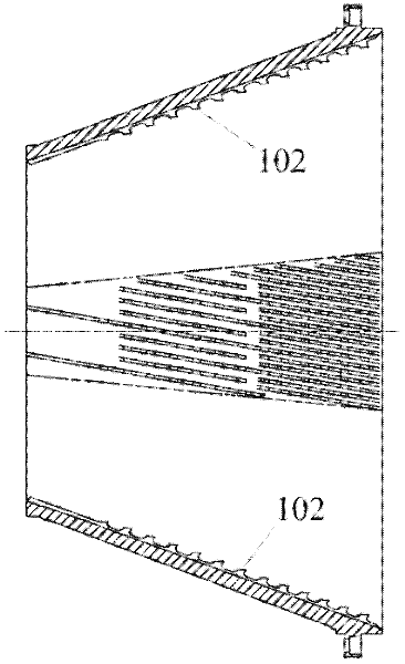
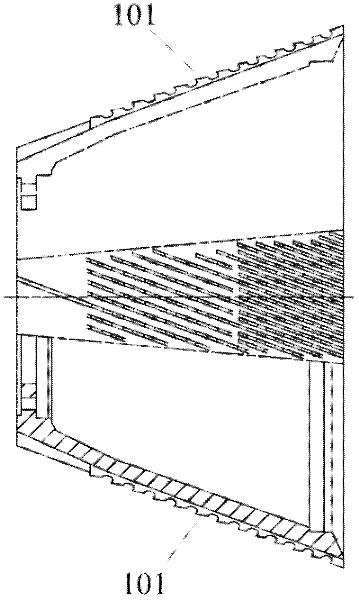
[0060] Figure 1A and Figure 1B The stator and rotor of a disperser are shown respectively, together with an example of conical refiner blade elements used in the disperser. The stator and rotor are shown in section. The first refiner surface, blade surface 101 is located in the rotating rotor of the refiner, disperser or defibrator and the second refiner surface is located in the stationary stator of the refiner, disperser or defibrator middle. The refiner surfaces can be formed directly as part of the stator / rotor or they can be made as separate blade segments or blade sections in a manner known in the art. The refiner surface comprises blade bars and grooves between the blade bars.

[0061] The refiner blade element may be in the shape of a plate, cylinder, cone, partially planar surface, partially cylindrical surface, partially conical surface or any combination of these.

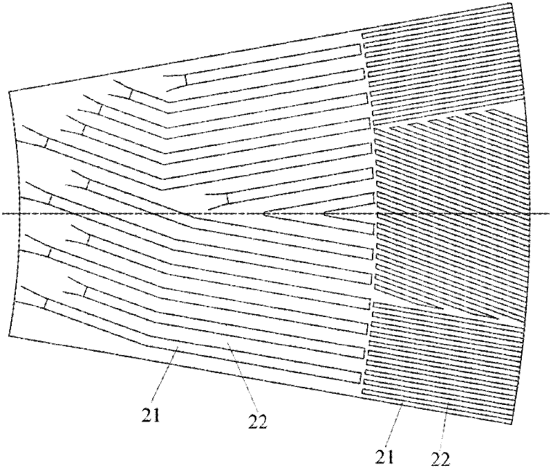
[0062] figure 2 A plan view showing an example of a plate refiner blade element. A plurality...


PUM

PropertyMeasurementUnit
widthaaaaaaaaaa
widthaaaaaaaaaa
widthaaaaaaaaaa

Abstract

The invention relates to a method for coating a wear part, the use of a wear part coated according to the method, a wear part and a refiner. According to the invention, at least part of the wear part surface is treated with an organic-inorganic sol-gel material, and the surface is hardened.

Description

technical field [0001] This invention relates to coatings for metallic wear parts. In particular, the present invention relates to the coating of wearing parts for use in processing fibrous slurry mixtures to prevent fouling and clogging. Background technique [0002] The blades of high-consistency refiner, low-consistency refiner, fiberboard refiner and disperser can be made of two or Multiple cast or welded bodies are formed. Alternatively, the blades may be constructed from smaller components, such as conical or cylindrical segments combined to form a rotationally symmetrical blade surface. The blade is fixed to the conical or flat body, for example by means of bolts. [0003] In this context, "blade element" means a blade, part-blade or corresponding part of a refiner, fibreboard refiner, disperser or defibrator. Where the blade is comprised of multiple components, the words "knife segment" or "blade portion" may be used to refer to these components. [0004] Wood f...

Claims


Application Information

Patent Timeline
Patent Type & Authority Applications(China)
IPC IPC(8): D21B1/34D21D1/30D21D5/02D21G3/00
CPCD21B1/345D21D1/306D21D5/02D21G3/00C23C18/1254D21D1/20D21D5/16
Inventor M.卡里奥
Owner VALMET TECH OY
Why Eureka
Try Eureka