Multi-stage turbocharger arrangement

A technology of turbochargers and superchargers, which is applied to gas turbine devices, machines/engines, combustion engines, etc., and can solve problems such as exhaust leakage

Inactive Publication Date: 2012-05-16
BORGWARNER INC
View PDF9 Cites 5 Cited by
  • Summary
  • Abstract
  • Description
  • Claims
  • Application Information

AI Technical Summary

Problems solved by technology

In prior art multi-stage turbocharger arrangements, these multi-stage turbocharger arrangements have an air gap to reduce heat transfer between the exhaust gas flow duct and the turbine housing, and these multi-stage turbocharger The compressor arrangemen

Method used


Image

  • Multi-stage turbocharger arrangement
  • Multi-stage turbocharger arrangement
  • Multi-stage turbocharger arrangement

Examples


Embodiment Construction

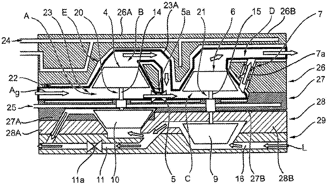
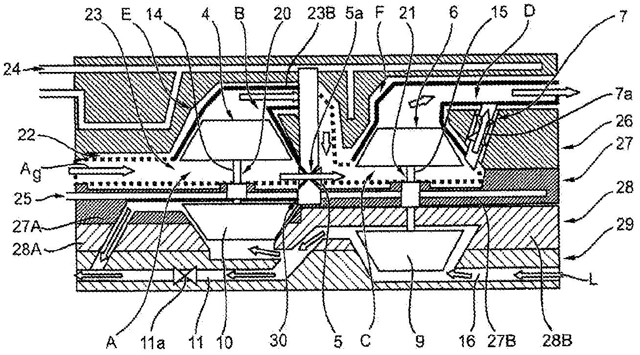
[0011] see figure 1 , a first embodiment of the multi-stage turbocharger arrangement 1 according to the invention will be described below. as from figure 1 As can be seen in the figure, the multistage turbocharger arrangement 1 has a high-pressure turbocharger 20 and a low-pressure turbocharger 21, the high-pressure turbocharger has a high-pressure turbine 4, which is connected via a shaft 14 to a on the high-pressure compressor 10; and the low-pressure turbocharger has a low-pressure turbine 6 connected via a shaft 15 to a low-pressure compressor 9. The high-pressure turbine 4 and the low-pressure turbine 6 are arranged in a common turbine housing unit 26, which is divided into a turbine housing section 26A of the high-pressure turbocharger 20 and the low-pressure turbine A turbine housing section 26B of the supercharger 21 . An inner casing 23 , which can expand due to heat, is inserted inside the turbine housing unit 26 , inside which hot engine exhaust gas Ag flows thro...


PUM


Abstract

The present invention relates to a multi-stage turbocharger arrangement (1), having a high-pressure turbocharger (20) which has a turbine housing (26A), a bearing housing (27A), a compressor housing (28A); and having a low-pressure turbocharger (21) which has a turbine housing (26B), a bearing housing (27B), a compressor housing (28B); wherein the turbine housings (26A, 26B) are provided with an integrated inner shell (23) for conducting exhaust gas.

Description

technical field [0001] The invention relates to a multi-stage turbocharger arrangement for an internal combustion engine according to the preamble of claim 1 . Background technique [0002] Conventional multi-stage turbocharger arrangements known from the prior art generally consist of at least two turbochargers arranged in series. Exhaust gas leakage occurring in the system, in particular downstream of a closed high-pressure turbine bypass valve, prevents the turbocharger arrangement from functioning optimally in all operating states. In the prior art, said leakage is prevented in that the bypass valve used has a very slight leakage at the valve seat. In prior art multi-stage turbocharger arrangements, these multi-stage turbocharger arrangements have an air gap to reduce heat transfer between the exhaust gas flow duct and the turbine housing, and these multi-stage turbocharger The compressor arrangement has a high-pressure turbine bypass valve also surrounded by an air ga...

Claims


Application Information

Patent Timeline
IPC IPC(8): F02B37/013F02B39/00F01D11/04F01D25/16
CPCF05D2240/40F02B37/013F02B37/127F01D25/162Y02T10/144F02B37/16F02B37/004F01D25/24F02B39/00F02C6/12F05B2240/40F02B37/18F02B37/22F01D17/105F01D25/125F01D25/14F02B39/005F05D2230/53F02B37/162Y02T10/12F01D11/04F01D25/16
Inventor V·乔格T·齐纳尔T·克瑞汀格
Owner BORGWARNER INC
Why Eureka
Try Eureka