Lighting device, display apparatus, and television receiving equipment
A technology for lighting devices and display devices, applied in the fields of display devices, television receivers, and lighting devices, can solve the problems of increased cost of backlight source devices, inability to increase brightness, and increased number of light sources, etc., so as to improve visual recognition and visual recognition. Excellent effect
- Summary
- Abstract
- Description
- Claims
- Application Information
AI Technical Summary
Problems solved by technology
Method used
Image

Examples
Embodiment approach 1
[0072] use Figure 1 to Figure 11 Embodiment 1 of the present invention will be described.
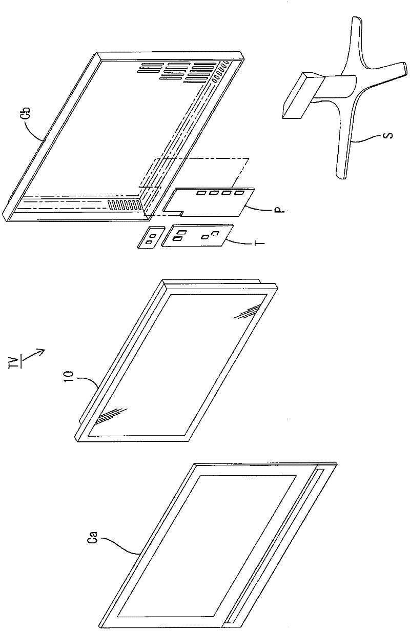
[0073] First, the configuration of a television receiver TV including a liquid crystal display device 10 will be described.
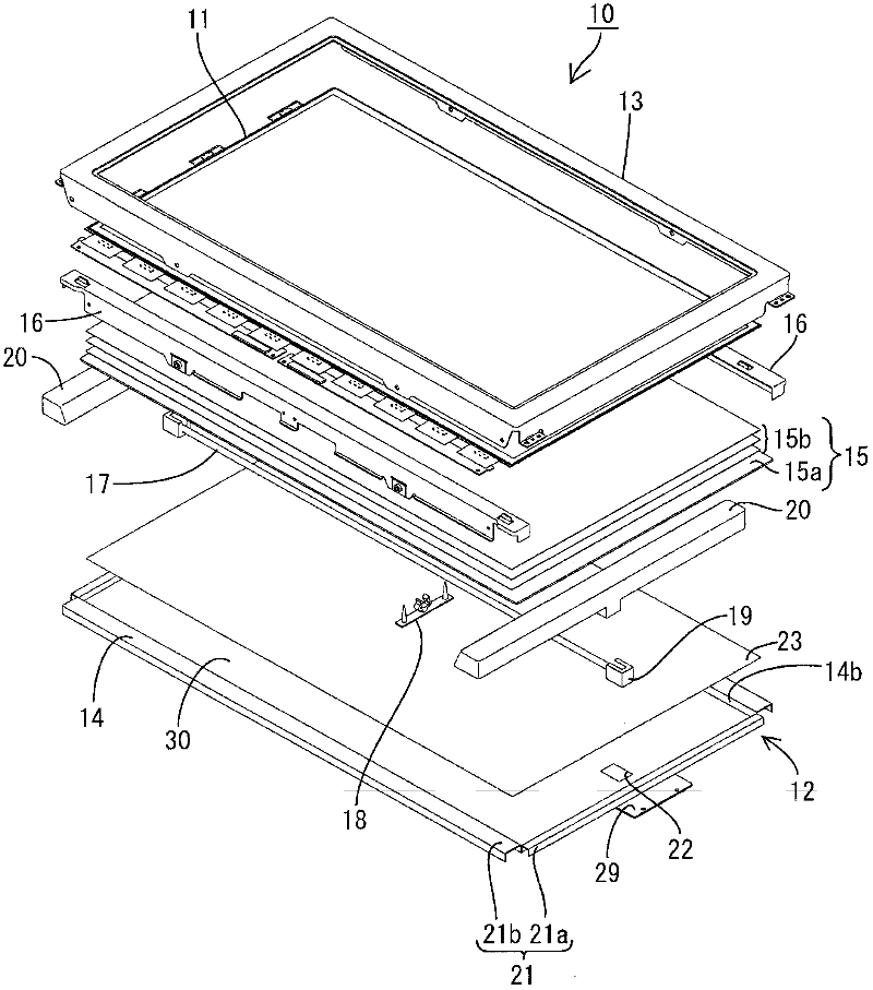
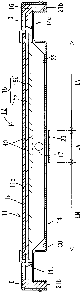
[0074] Such as figure 1 As shown, the television receiver TV of the present embodiment is configured to include: a liquid crystal display device 10, two front and back cabinets Ca, Cb for accommodating the liquid crystal display device 10 so as to sandwich the liquid crystal display device 10, a power supply P, and a tuner. T and pedestal S. The liquid crystal display device (display device) 10 has a horizontally long rectangular shape as a whole, and is housed in a vertical state. Such as figure 2 As shown, this liquid crystal display device 10 includes a liquid crystal panel 11 as a display panel and a backlight device (illumination device) 12 as an external light source, and these are integrally held by a frame-shaped outer frame 13 or the like.
[007...
Embodiment approach 2
[0119] Next, use Figure 16 and Figure 17 Embodiment 2 of the present invention will be described. In this second embodiment, the configuration of the light source is changed from that of the first embodiment, and the rest are the same as those of the above-mentioned first embodiment. The same reference numerals are assigned to the same parts as those in Embodiment 1 above, and overlapping descriptions will be omitted.
[0120] Figure 16 is a plan view showing a schematic configuration of a chassis included in the backlight unit, Figure 18 It is a schematic diagram showing the arrangement form of the light reflection part formed on the surface of the diffuser plate facing the cold cathode tubes.
[0121] The cold-cathode tubes 70 are elongated tubes with a diameter of 4.0 mm, and are arranged parallel to each other in a plurality (here, six) in a state where the longitudinal direction (axial direction) is consistent with the long-side direction of the base 14. The stat...
Embodiment approach 3
[0129] Next, use Figure 18 to Figure 20 Embodiment 3 of the present invention will be described. In this Embodiment 3, the disposition form of the light source is further changed from that of Embodiment 1, and the others are the same as those of Embodiment 1 described above. The same reference numerals are assigned to the same parts as those in Embodiment 1 above, and overlapping descriptions will be omitted.
[0130] Figure 18 is an exploded perspective view showing a schematic configuration of a liquid crystal display device, Figure 19 It is a schematic plan view of a base showing an arrangement form of an LED light source, Figure 20 It is a schematic diagram showing the arrangement form of the light reflection part formed on the surface facing the LED light source in the diffuser plate.
[0131] Such as Figure 18 As shown, an LED substrate 81 is arranged on the inner surface side of the bottom plate 33 of the chassis 14 , and an LED light source (light source) 80 ...
PUM
| Property | Measurement | Unit |
|---|---|---|
| porosity | aaaaa | aaaaa |
| hazing | aaaaa | aaaaa |
| reflectivity | aaaaa | aaaaa |
Abstract
Description
Claims
Application Information
 - R&D
- Intellectual Property
- Life Sciences
- Materials
- Tech Scout
- Unparalleled Data Quality
- Higher Quality Content
- 60% Fewer Hallucinations
Browse by: Latest US Patents, China's latest patents, Technical Efficacy Thesaurus, Application Domain, Technology Topic, Popular Technical Reports.
© 2025 PatSnap. All rights reserved.Legal|Privacy policy|Modern Slavery Act Transparency Statement|Sitemap|About US| Contact US: help@patsnap.com