

Wiring board and power conversion device
A technology of power conversion devices and wiring substrates, which is applied in the direction of conversion equipment structural parts, circuits, electrical components, etc., and can solve the problems of ineffective heat dissipation of power conversion devices
- Summary
- Abstract
- Description
- Claims
- Application Information
AI Technical Summary
Problems solved by technology
Method used
Image

Examples
no. 1 Embodiment approach
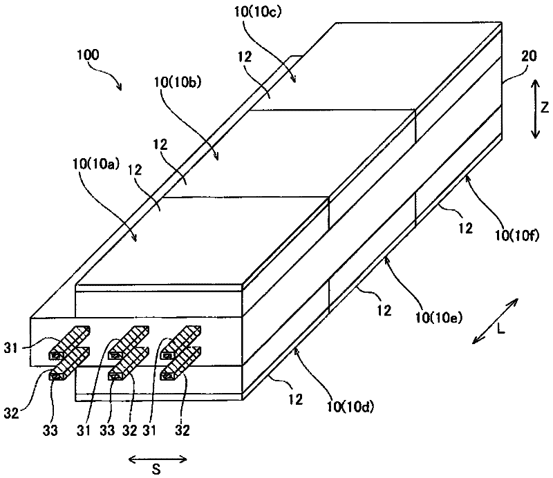
[0094] First, refer to Figure 1 to Figure 10 The overall structure of the power conversion device 100 including the wiring board 20 according to the first embodiment of the present invention will be described. In addition, in the first embodiment, an example in which the present invention is applied to a wiring board of a power conversion device as an example of the "wiring board" of the present invention will be described.
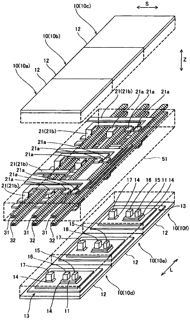
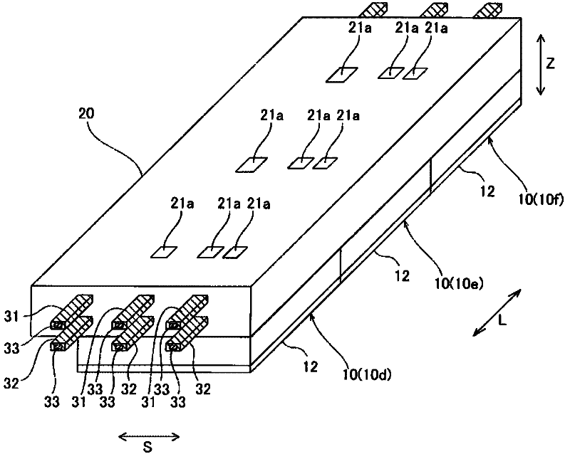
[0095] Such as Figure 1 ~ Figure 3 As shown, the power conversion device 100 includes: six power modules 10; Three power modules 10 a , 10 b , and 10 c are arranged on the upper surface side of wiring board 20 , and three power modules 10 d , 10 e , and 10 f are arranged on the lower surface side of wiring substrate 20 . Such as Figure 4 As shown, six power modules 10a to 10f are connected in parallel to form three sets of two, thereby constituting a three-phase full-bridge circuit.
[0096] Each of the six power modules 10 (10a to 10f) has the sam...
no. 2 Embodiment approach
[0116] Below, refer to Figure 11 The second embodiment will be described. In this second embodiment, a metal plate (refer to Figure 10 ) Unlike the above-described first embodiment, which forms the conductor plates 21 and 22 of the wiring board 20 , a conductor plate 121 ( 122 ) obtained by bundling a plurality of conductor wires 123 into a plate shape is employed. In addition, the structure of the wiring board is the same as that of the above-mentioned first embodiment, so description thereof will be omitted. In addition, the conductor plates 121 and 122 are examples of the “first conductor plate” and the “second conductor plate” of the present invention, respectively.
[0117] Such as Figure 11 As shown, the conductor plate 121 (122) is provided on the wiring board of the second embodiment instead of the conductor plate 21 (22) of the wiring board 20 of the first embodiment. The conductor plate 121 ( 122 ) is formed by bundling a plurality of conductor wires 123 into ...
no. 3 Embodiment approach
[0120] Below, refer to Figure 12 to Figure 14 The third embodiment will be described. In this third embodiment, unlike the conductor plate 21 (22) of the wiring board 20 of the above-mentioned first embodiment and the conductor plate 121 (122) of the above-mentioned second embodiment, a conductor plate 131 (132) is formed with A cooling structure constituted by cooling holes 137 . In addition, the conductor plates 131 and 132 are examples of the "1st conductor plate" and "2nd conductor plate" of this invention, respectively.
[0121] Such as Figure 12 As shown, in the third embodiment, a conductor plate 131 ( 132 ) including a cooling structure including cooling holes 137 is provided. Conductor plate 131 (132) includes wiring portion 139a composed of insulating layer 133, first layer conductor wiring 134, second layer conductor wiring 135, and third layer conductor wiring 136, and three electrode portions 139b, 139c, and 139d.
[0122] On the surface of the third-layer c...
PUM
 Abstract
Description
Claims
Application Information