
Automotive vehicle collision device with novel switch type jetting energy dissipater

A collision device and switch-type technology, which is applied in the direction of the bumper, can solve problems such as strain and fit gap leakage, and achieve the effects of protecting the head and chest, reducing frictional resistance, and protecting the lower limbs

Inactive Publication Date: 2012-05-23
凌建军
View PDF1 Cites 0 Cited by
  • Summary
  • Abstract
  • Description
  • Claims
  • Application Information

AI Technical Summary

Problems solved by technology

[0010] The purpose of the present invention is to solve the problem of strain caused by the line contact between the shuttle valve and the valve cylinder, not only to reduce the friction resistance during the rising process of the shuttle valve, but also to solve the problem of leakage caused by the fit gap

Method used


Image

  • Automotive vehicle collision device with novel switch type jetting energy dissipater
  • Automotive vehicle collision device with novel switch type jetting energy dissipater
  • Automotive vehicle collision device with novel switch type jetting energy dissipater

Examples


no. 1 approach

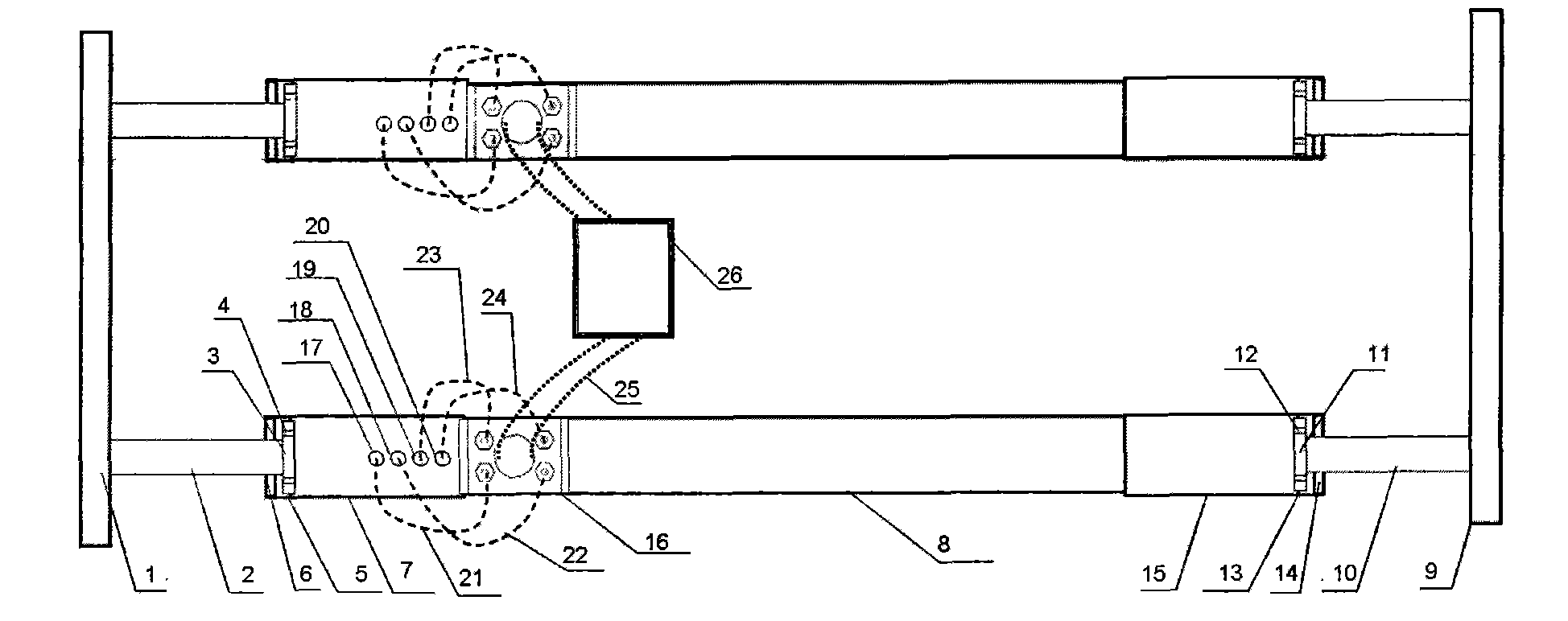
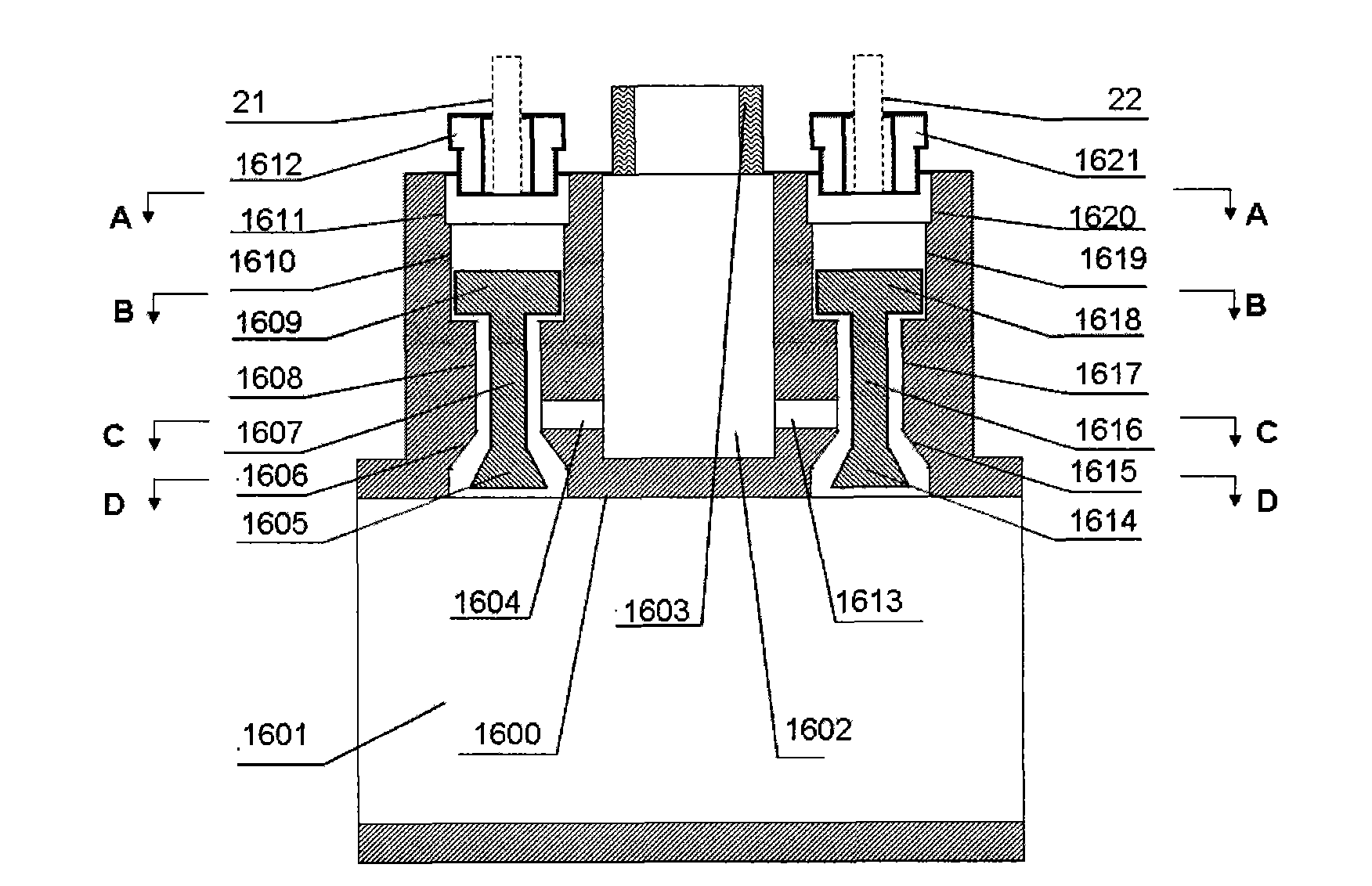
[0050] figure 1 It is a schematic cross-sectional view of a motor vehicle collision device with a novel switch-type injection energy consumer of the present invention; figure 2 It is a top view schematic diagram of a motor vehicle collision device with a novel switch-type injection energy consumer of the present invention; image 3 It is a schematic cross-sectional view of the novel switch type jet energy consumer of the present invention; Figure 4 It is a schematic top view of the novel switch type jet energy consumer of the present invention; Figure 5 It is a schematic cross-sectional view of the A-A plane of the novel switch type jet energy consumer of the present invention; Figure 6 It is a schematic sectional view of the B-B plane of the novel switch type jet energy consumer of the present invention; Figure 7 It is a schematic cross-sectional view of the C-C plane of the novel switch type jet energy consumer of the present invention; Figure 8 It is a schematic d...

no. 2 approach

[0063] Figure 11 It is a cross-sectional view of the new switch-type injection energy consumer in the second embodiment of the present invention; the second embodiment is basically the same as the first embodiment, the only change is that the upper valve cylinder is changed from a cylinder to a circle with a tapered hole at the bottom cylinder, the upper shuttle valve has changed from a cylinder to a cone; that is, the fifth upper valve cylinder 1641 and the sixth upper valve cylinder 1643 are cylinders with tapered holes at the bottom; the fifth upper shuttle valve 1640 , The sixth upper shuttle valve 1642 is a cone.

no. 3 approach

[0065] Figure 12 It is a cross-sectional view of a new switch type jet energy consumer according to the third embodiment of the present invention.

[0066] The third embodiment is basically the same as the first embodiment, the only change is that the lower valve cylinder has changed from a cylinder with a tapered hole on the top to a cylinder, and the lower shuttle valve has changed from a cone to a cylinder; The fifth lower valve cylinder 1645 and the sixth lower valve cylinder 1647 become cylinders; the fifth lower shuttle valve 1644 and the sixth lower shuttle valve 1646 become cylinders.


PUM


Abstract

The invention discloses an automotive vehicle collision device with a novel switch type jetting energy dissipater, which comprises a piston cylinder, a screw hole joint, a high pressure connection tube and the novel switch type jetting energy dissipater, wherein the novel switch type jetting energy dissipater comprises a high pressure buffer chamber, a low pressure buffer chamber, a pedestal jetting hole, an upper part valve cylinder, a middle part valve cylinder, a lower part valve cylinder, an upper part shuttle valve, a middle part shuttle valve and a lower part shuttle valve; the pedestal jetting hole penetrates from the middle part valve cylinder to the low pressure buffer chamber; a liquid channel is arranged between the middle part valve cylinder and the middle part shuttle valve; a liquid channel is arranged between the lower part valve cylinder and the lower part shuttle valve; and each shuttle valve assembly can vertically shuttle according to a pressure difference between the upper end and the lower end, so that the corresponding liquid channel between the lower part valve cylinder and the lower part shuttle valve is closed. According to the automotive vehicle collision device with the novel switch type jetting energy dissipater, the contact strain problem and the loss problem of wires between the shuttle valve and the valve cylinder can be solved, the automotive vehicle can be ensured to have a bidirectional anti-collision function, and the automotive vehicle body can be ensured to be always in a stretching state.

Description

technical field [0001] The invention relates to a motor vehicle collision device, in particular to a motor vehicle collision device with a novel switch-type injection energy consumer. Background technique [0002] Since the advent of motor vehicles in 1886, while bringing convenience to human life and work, road traffic accidents have also caused a large number of casualties and property losses. So far, more than 34 million people have died in car accidents worldwide, while hundreds of millions of people have been injured or disabled. According to the "Global Status of Road Safety" report published by the World Health Organization (WHO) on June 15, 2009, the number of deaths involving road traffic accidents in 2008 was as high as 1.2 million, and 20 to 30 million were injured or disabled. The annual economic loss caused by traffic accidents exceeds 700 billion US dollars. [0003] The body of the existing motor vehicle is in a compressed state during the collision process....

Claims


Application Information

Patent Timeline
Patent Type & Authority Applications(China)
IPC IPC(8): B60R19/32
Inventor 凌建军杨铸李越黄鹂凌阁
Owner 凌建军
Learn More