Jig dyeing machine

A technology of jiggers and racks, which is applied in the field of jiggers, and can solve problems such as fabric breakage, cloth congestion, and excessive tension

Inactive Publication Date: 2012-05-23
包德全
View PDF0 Cites 1 Cited by
  • Summary
  • Abstract
  • Description
  • Claims
  • Application Information

AI Technical Summary

Problems solved by technology

[0002] Existing AC variable frequency dyeing jiggers only rely on decreasing frequency to stop and slow down. Since the jigger is running at a high speed, there is a lot of inertial kinetic energy in the cloth roll and the cloth roll. If the frequency decreases too fast, it will easily cause the rear roll to run fast and choke the cloth. , or the fabric is broken due to excessive tension, which is the bottleneck that restricts the performance of the jigger
In addition, in some underdeveloped areas, due to cost factors and power quality factors, it is difficult to properly apply frequency conversion technology

Method used


Image

  • Jig dyeing machine
  • Jig dyeing machine
  • Jig dyeing machine

Examples


Embodiment Construction

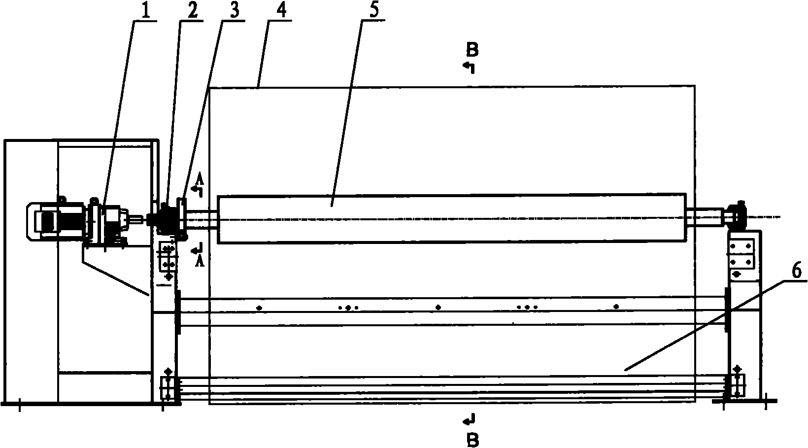
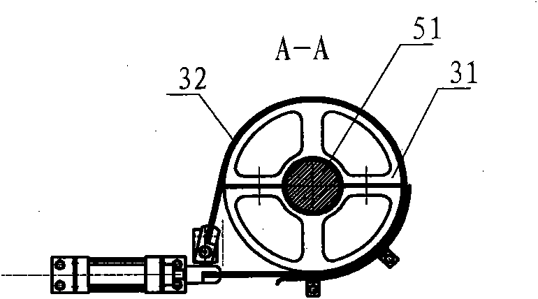
[0014] The present invention as Figure 1-3 As shown, it includes a frame 2, and a pair of cloth winding rollers 5 are arranged horizontally for laying and rewinding the cloth. The frame 2 is provided with a braking device 3 corresponding to the head 51 of the cloth winding roller 5.

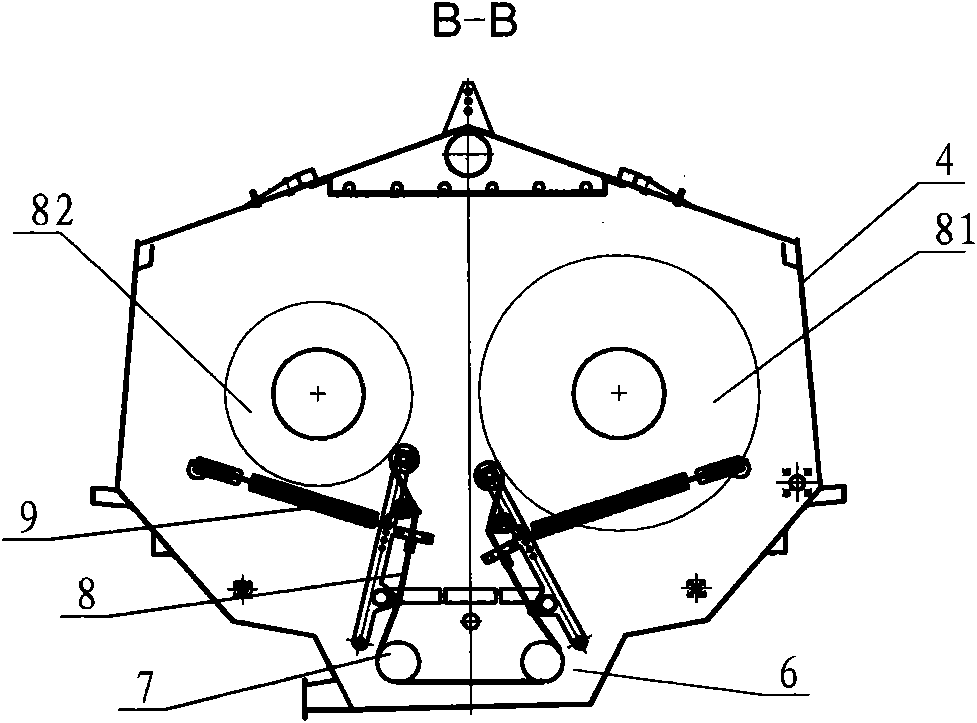
[0015] The pair of cloth rolling rollers 5 are provided with a cover body 4 outside, and the lower part of the cover body 4 is provided with a immersion tank 6 , and the head 51 of the cloth rolling roller protrudes out of the cover body 4 .

[0016] It also includes a controller, and the braking device 4 includes an electric, hydraulic or pneumatic driving device, and the electric, hydraulic or pneumatic driving device is connected to the controller.

[0017] Wherein the braking mechanism part of braking device 4 can adopt such as image 3 Form brake hub 31, brake band 32, the drive mechanism that drives brake band 32 can be aforementioned electric, hydraulic or pneumatic. The controller calc...


PUM


Abstract

The invention relates to improvement on a cloth roller driving mechanism of a jig dyeing machine. Through the improvement, the inertia of a large yardage roll can be prevented from acting on a small yardage roll at the final stage of cloth reeling so as to prevent cloth blockage and breakage. The jig dyeing machine comprises a frame and a pair of horizontal cloth rollers which ensure that cloths are put around each other, wherein a braking device corresponding to a roller head of the cloth rollers is arranged on the frame. Compared with the prior art, the jig dyeing machine has the advantages that a deceleration braking device is arranged at the roller head (spindle head) of the cloth rollers, and the technical problems that the idle period of a variable-frequency jig dyeing machine is too long after one process step so head-tail chromatic aberration is caused, invalid work is caused by overlong head cloth, dyes, chemicals, water, electricity and steam are wasted, and environmental pollution and energy waste are caused are solved. The braking device can rapidly and smoothly decelerate and then stop a high-speed running yardage roll particularly a giant yardage roll (phi1400) so as to solve the problems existing when the conventional jig dyeing machine particularly a giant jig dyeing machine quickly stops. The improvement is suitable for a variable-frequency jig dyeing machine, a direct-current jig dyeing machine, a normal-temperature jig dyeing machine and a high-temperature jig dyeing machine.

Description

technical field [0001] The invention relates to a dyeing jigger in the textile printing and dyeing industry, and in particular relates to the improvement of the transmission mechanism of the fabric winding roller of the dyeing jigger. Background technique [0002] Existing AC variable frequency dyeing jiggers only rely on decreasing frequency to stop and slow down. Since the jigger is running at a high speed, there is a lot of inertial kinetic energy in the cloth roll and the cloth roll. If the frequency decreases too fast, it will easily cause the rear roll to run fast and choke the cloth. , or the fabric is broken due to excessive tension, which is the bottleneck restricting the performance of the jigger. In addition, in some underdeveloped areas, due to cost factors and power quality factors, it is difficult to properly apply frequency conversion technology. Contents of the invention [0003] In view of the above problems, the present invention provides a jigger which ...

Claims


Application Information

Patent Timeline
Patent Type & Authority Applications(China)
IPC IPC(8): D06B3/32D06B3/36
Inventor 包德全
Owner 包德全
Why Eureka
Try Eureka