Configuration structure of variable valve lift mechanism and oil controlled valve of engine

An oil control valve seat and oil control technology, applied in valve devices, non-mechanically actuated valves, mechanical equipment, etc., can solve problems such as engine embrittlement and damage, complicated assembly, and oil drainage

Inactive Publication Date: 2014-06-11
KYMCO
View PDF6 Cites 0 Cited by
  • Summary
  • Abstract
  • Description
  • Claims
  • Application Information

AI Technical Summary

Problems solved by technology

[0003] Conventional engine 1 is by the setting of this electromagnetic valve 2 and oil pipe 21, although can reach the intake and exhaust valve switching of different lifts when cooperating with engine 1 high and low speed operation, yet, because electromagnetic valve 2 is locked with several screws 22 It is attached to the cylinder head 11, so it is relatively complicated to assemble, and the oil pipe 21 externally connected to the solenoid valve 2 has the fear of oil leakage, and it is exposed outside the engine 1, so it is easy to burn due to the high temperature of the engine 1. Embrittlement and damage will occur. In addition, since the solenoid valve 2 is arranged above the cylinder head 11, it is easy to cause the solenoid valve 2 to interfere with the upper parts such as the glove box when the engine 1 is swinging.

Method used


Image

  • Configuration structure of variable valve lift mechanism and oil controlled valve of engine
  • Configuration structure of variable valve lift mechanism and oil controlled valve of engine
  • Configuration structure of variable valve lift mechanism and oil controlled valve of engine

Examples


Embodiment Construction

[0054] In order to make it easier to understand the structure of the present invention and the effect that can be achieved, it is described as follows in conjunction with the drawings:

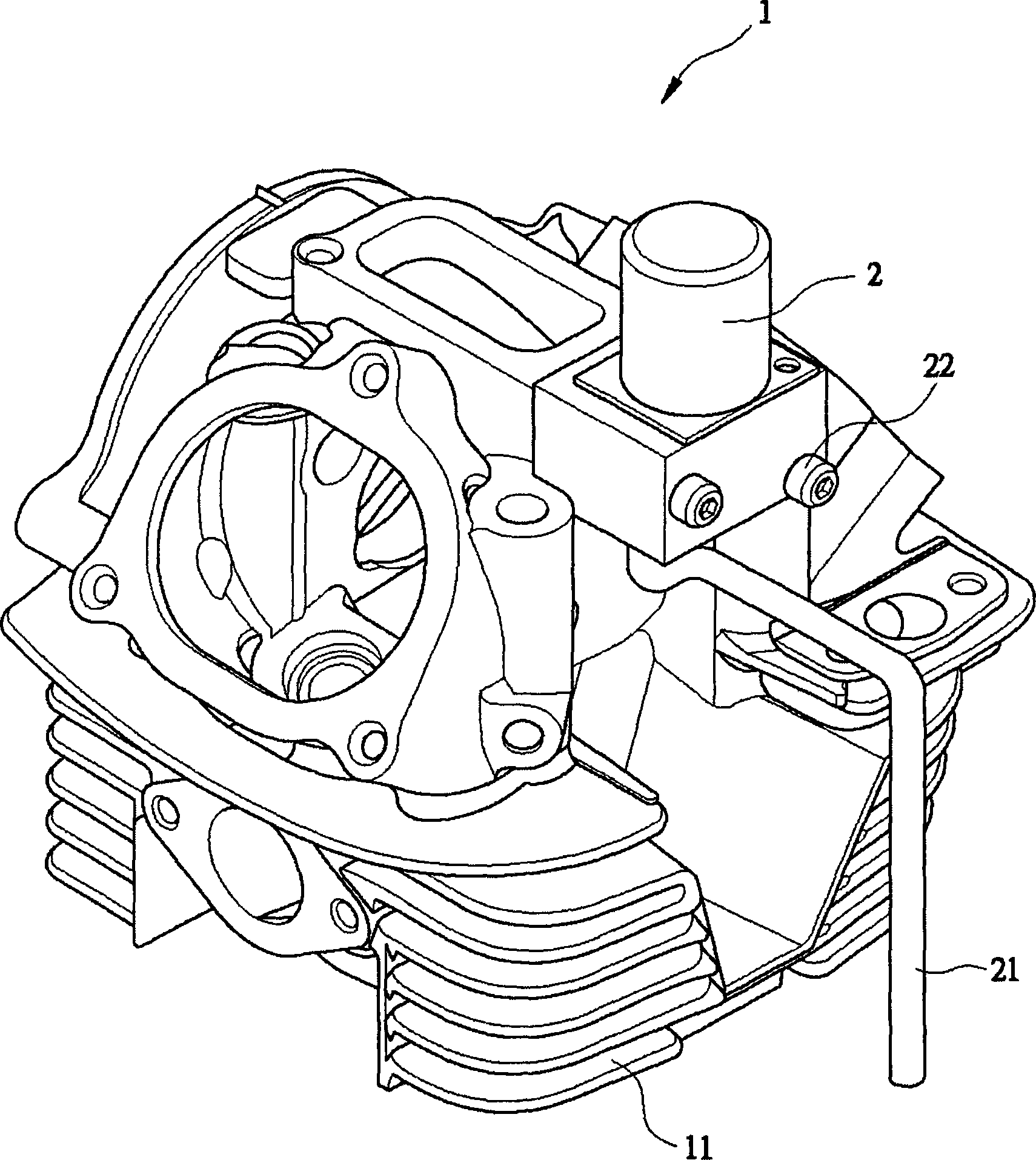
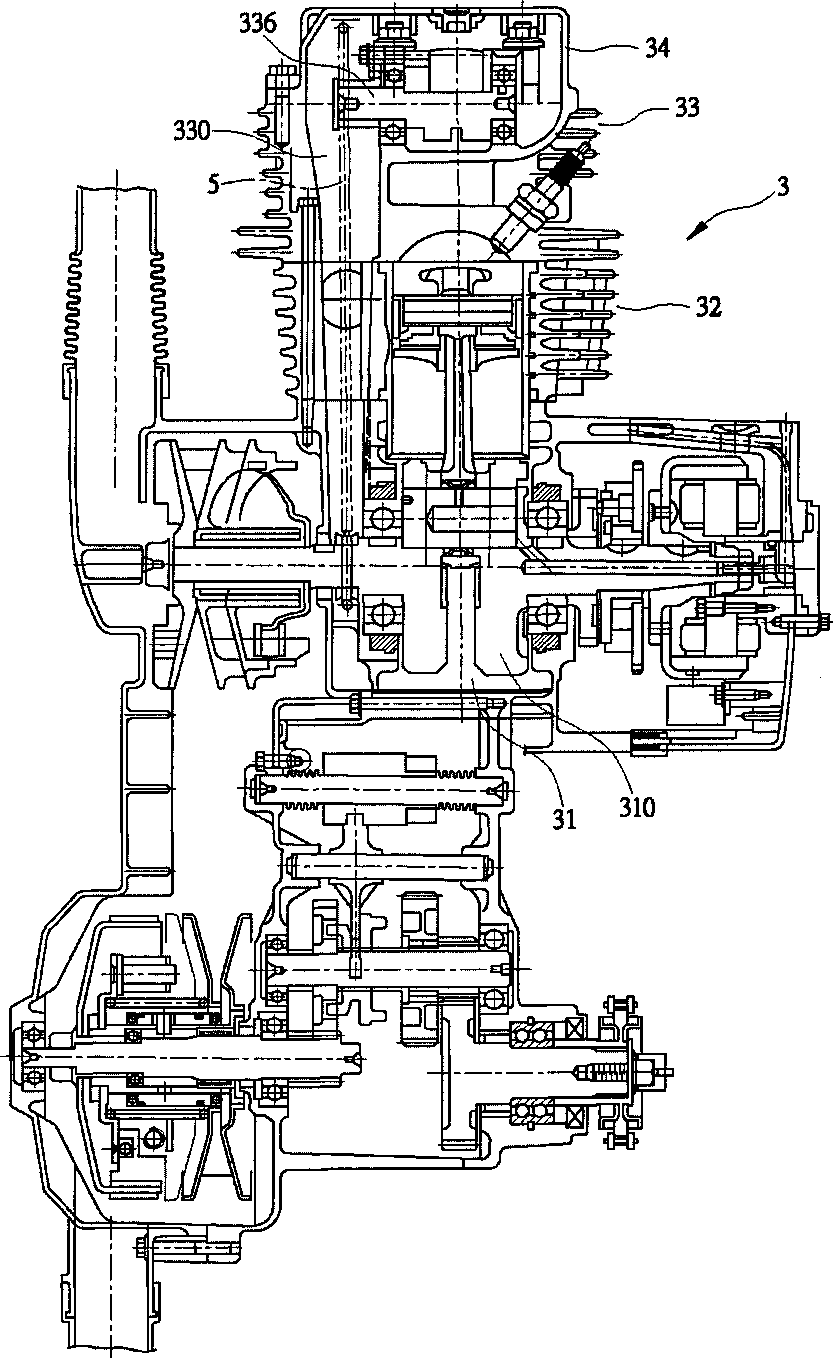
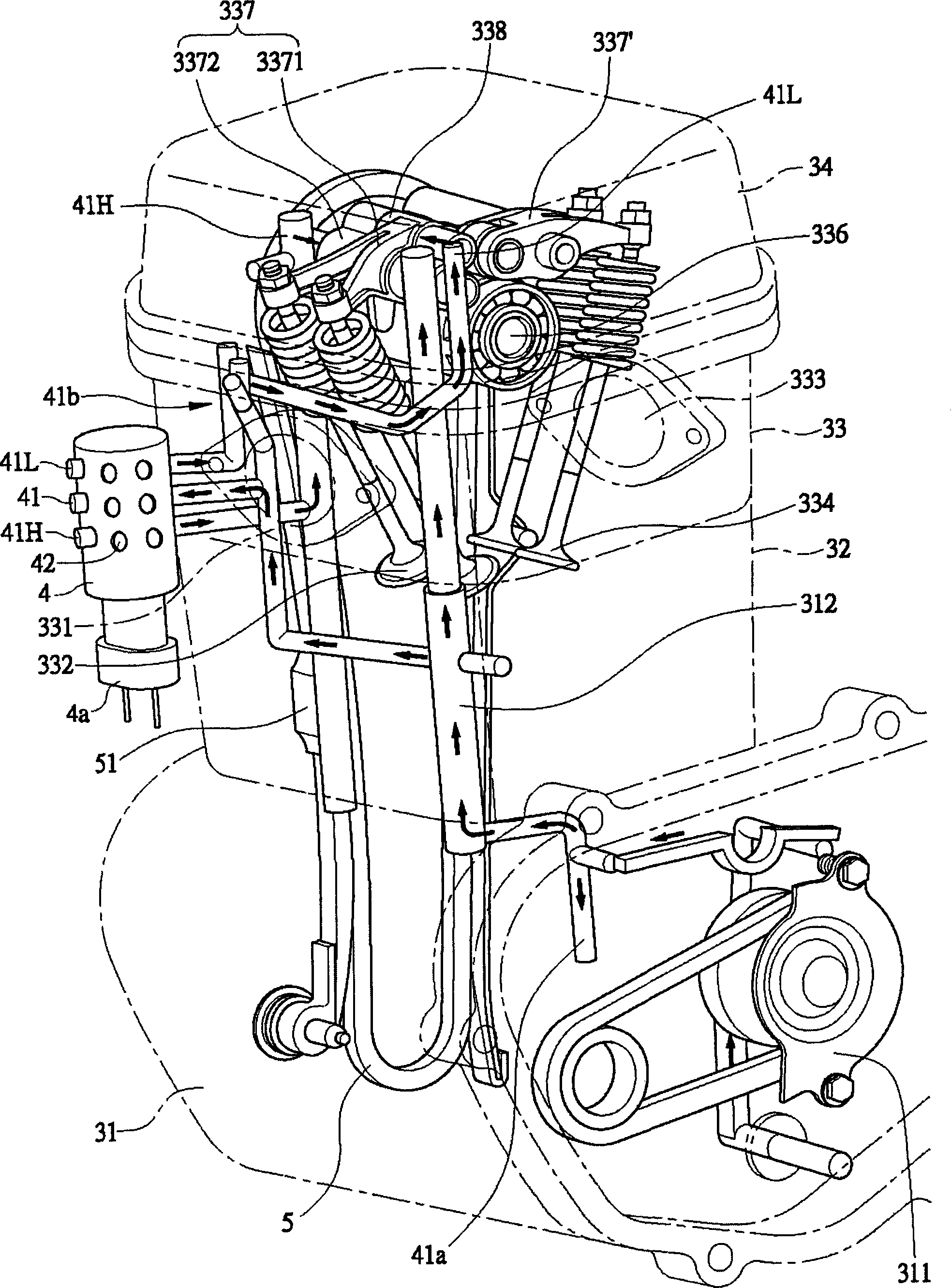
[0055] The engine 3 of the present invention is a swing engine 3 arranged on a scooter motorcycle in a substantially horizontal manner. First, see figure 2 As shown, the engine 3 of the present invention has a crankcase 31, a group of cylinder body 32 arranged on the crankcase 31, a group of cylinder head 33 and cylinder head cover 34 arranged on the cylinder body 32. Crankcase 31, inside is provided with a crankshaft 310, please cooperate image 3 Refer to, the crankcase 31 is provided with an oil pump 311, the oil pump 311 sends the oil to a main oil supply channel 312, and the main oil supply channel 312 is connected to the cylinder head after the crankcase 31 passes through the cylinder body 32. 33 oil control valve 4.

[0056] Cylinder body 32, this cylinder body 32 is connected on th...


PUM


Abstract

The invention discloses a configuration structure of a variable valve lift mechanism and an oil controlled valve of an engine. The engine is provided with a cylinder head, one side of the cylinder head is provided with a gas inlet and a gas inlet valve, the other side of the cylinder head is provided with an exhaust hole and an exhaust valve, a throttling valve body penetrates through a gas inlet pipe to be communicated with the gas inlet, a cam shaft seat is arranged between the gas inlet valve and the exhaust valve and provided with a cam shaft, the cam shaft is provided with a gas inlet cam and an exhaust cam which can push a gas inlet valve push member and an exhaust valve push member, the gas inlet cam is provided with a first gas inlet cam and a second gas inlet cam, the gas inlet valve push member is provided with a low-lift push member and a high-lift push member corresponding to the first gas inlet cam and the second gas inlet cam respectively, the low-lift push member and the high-lift push member are provided with oil hydraulic cylinders which are communicated, pistons are arranged in the oil hydraulic cylinders; and the oil controlled valve is provided with a drive oil path communicated with the oil hydraulic cylinders, a lower-lift push member of the high-lift push member is closer to the oil controlled valve, and a path of a drive oil path of the oil controlled valve and the high-lift push member is shorter than that of a drive oil path of driving the low-lift push member by the oil controlled valve.

Description

【Technical field】 [0001] The invention relates to an arrangement structure of an engine variable valve lift mechanism and an oil control valve, especially to prevent the oil control valve from interfering with the maintenance of other parts, and to perform up and down lift movements by the valve pusher of the engine, and then A structure that can reduce the size of the oil pump and reduce the loss of engine power. 【Background technique】 [0002] The known variable valve lift mechanism oil circuit configuration structure of the engine 1, please refer to figure 1 As shown, a solenoid valve 2 is set above the cylinder head 11, and the lubricating oil at the oil pressure inlet is directly introduced into the solenoid valve 2 through the pipeline 21, and then the solenoid valve 2 Lubricating oil is introduced into the oil circuit in the cylinder head 11, and the variable lift mechanism of each cylinder is driven by the oil pressure to switch the intake and exhaust valves of diff...

Claims


Application Information

Patent Timeline
Patent Type & Authority Patents(China)
IPC IPC(8): F01L13/00F01L9/02F01L1/348F02F1/42F16H7/08F01L9/10
Inventor 丁荣丰
Owner KYMCO
Why Eureka
Try Eureka