
Industrial constant temperature control system

A constant temperature control, industrial technology, applied in control systems, steam generation, lighting and heating equipment, etc., can solve the problems of low degree of intelligence, can not meet the actual needs of use, difficult, etc., to achieve a high degree of intelligence, practical High value and low energy consumption

Inactive Publication Date: 2012-05-23
XIAN KUOLI MACHANICAL & ELECTRICAL TECH
View PDF0 Cites 9 Cited by
  • Summary
  • Abstract
  • Description
  • Claims
  • Application Information

AI Technical Summary

Problems solved by technology

[0005] The technical problem to be solved by the present invention is to provide an industrial constant temperature control system with simple structure, reasonable design, convenient installation and layout, easy operation, high degree of intelligence and good use effect in view of the deficiencies in the above-mentioned prior art. It can effectively solve various practical problems such as the low degree of intelligence of the existing steam heater temperature control system, the difficulty in adjusting the control parameters from high temperature to low temperature under continuous working conditions, and the inability to meet actual use requirements.

Method used


Image

  • Industrial constant temperature control system
  • Industrial constant temperature control system
  • Industrial constant temperature control system

Examples


Embodiment Construction

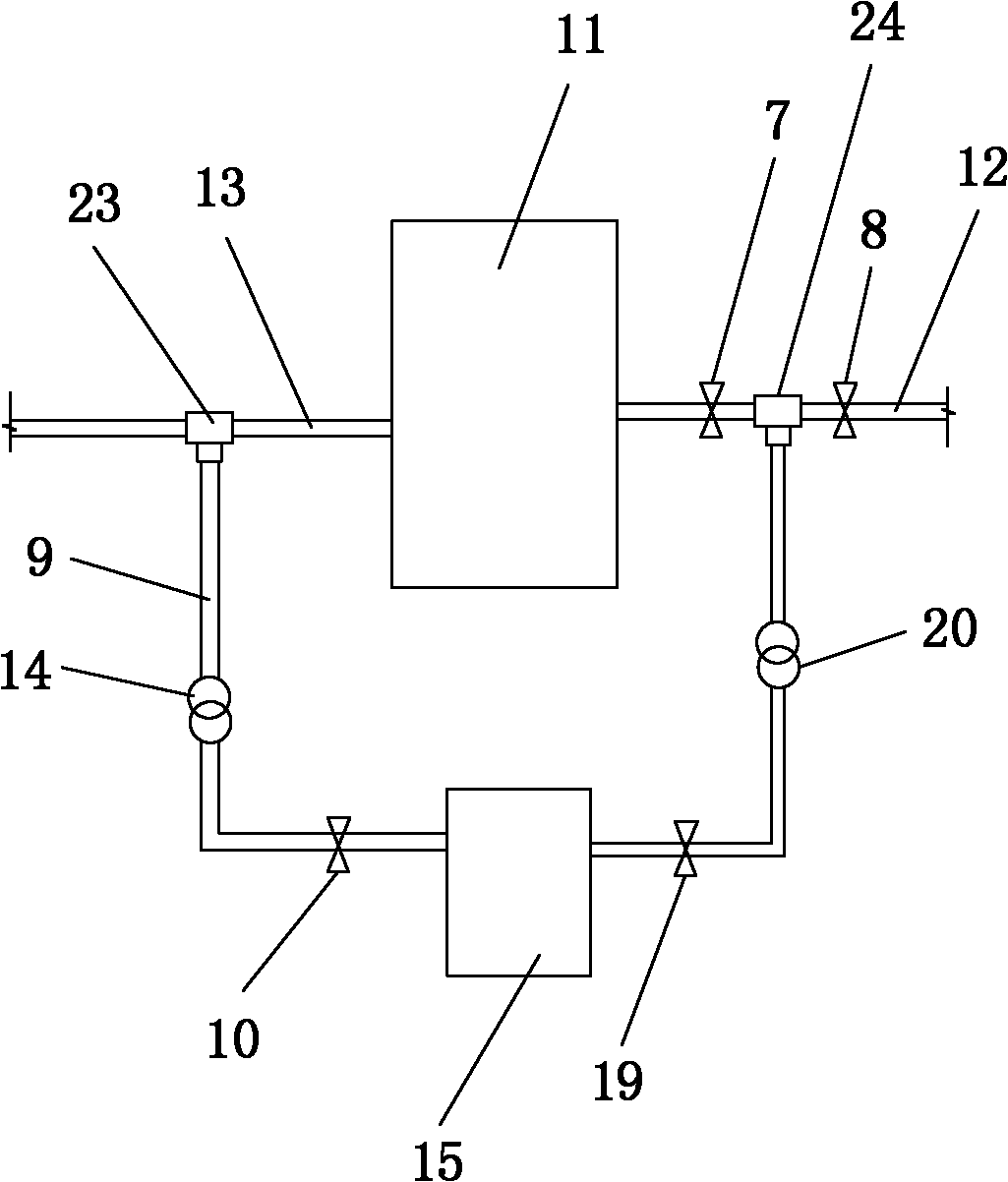
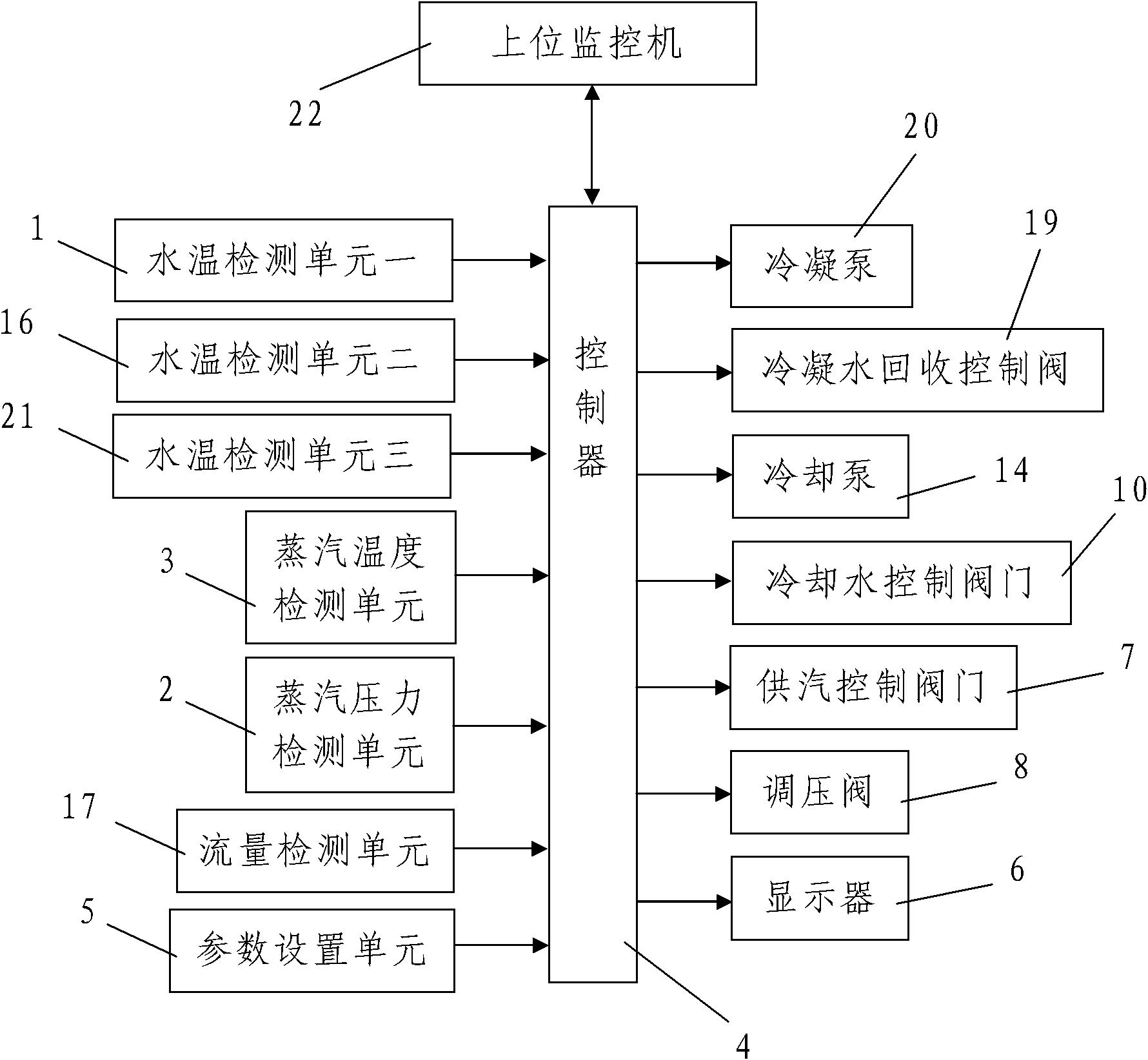
[0033] Such as figure 1 , figure 2 As shown, the present invention includes a water temperature detection unit-1 for real-time detection of the water temperature at the water outlet of the steam heater 11, and real-time detection of the pressure and temperature of the steam provided in the steam supply pipeline 12 connected to the steam heater 11 respectively. The steam pressure detection unit 2 and the steam temperature detection unit 3, the cooling water tank 15, the cooling water supplementary pipeline 9 connected between the cooling water tank 15 and the steam heater 11 connected to the water supply pipeline 13, are installed on the cooling water supplementary pipeline 9 And the cooling water control valve 10 and the cooling pump 14 controlled by the controller 4, the water temperature detection unit 2 16 for real-time detection of the water temperature in the cooling water tank 15, the flow detection for real-time detection of the flow of the cooling water replenishment ...


PUM


Abstract

The invention discloses an industrial constant temperature control system. The industrial constant temperature control system comprises a water temperature detection unit 1, a steam pressure detection unit, a steam temperature detection unit, a cooling water tank, a cooling water supplement pipeline, a cooling water control valve, a cooling pump, a water temperature detection unit 2, a flow rate detection unit, a controller, a parameter setting unit and a display, wherein the water temperature detection unit 1 is used for detecting the temperature of water at a water outlet of a steam heater; the steam pressure detection unit and the steam temperature detection unit are used for detecting the pressure and the temperature of steam supplied by a steam supply pipeline; the cooling water supplement pipeline is connected between the cooling water tank and a water supply pipeline of the steam heater; the cooling water control valve and the cooling pump are arranged on the cooling water supplement pipeline and are controlled by the controller; the water temperature detection unit 2 is used for detecting the temperature of water in the cooling water tank; and the flow rate detection unit is used for detecting the flow rate of the cooling water supplement pipeline. The industrial constant temperature control system is reasonable in design and easy to operate, has high intelligence degree and a good using effect, and can effectively solve the actual problems that the conventional steam heater temperature control system has low intelligence degree, and difficultly adjusts high temperature control parameters to low temperature control parameters in a continuous operating state and the like.

Description

technical field [0001] The invention relates to an automatic control system, in particular to an industrial constant temperature control system. Background technique [0002] A boiler is a mechanical device that uses heat from fuel or other energy sources to heat water into hot water or steam. At present, the boilers used in the market are divided into steam boilers, hot water boilers and steam-water dual-purpose boilers according to the state of the outlet medium. At present, the high-pressure heaters and low-pressure heater lamp heating equipment used in thermal power plants are all steam heaters. The above-mentioned steam heater is essentially a shell-and-tube heat exchanger, and the two tubes on the side of the tank are tube-side and The heated medium is generally water, the inlet and outlet of the tube side are water inlet and outlet respectively, and the top and bottom of the tank are respectively opened with steam inlet and steam outlet or condensate discharge outlet...

Claims


Application Information

Patent Timeline
Patent Type & Authority Applications(China)
IPC IPC(8): F22B35/00
Inventor 周晓丽
Owner XIAN KUOLI MACHANICAL & ELECTRICAL TECH
Learn More